Component and a gas turbine engine comprising the component

a gas turbine engine and component technology, applied in the direction of machines/engines, threaded fasteners, couplings, etc., can solve the problems of friction joints that require large clamping forces, parts that are unique and generally not replaceable, and the machining operation may be complex, so as to eliminate the problem of tolerance series or the elimination of the problem of tolerance chains. , the effect of eliminating the problem of tolerance series

Active Publication Date: 2011-12-08
GKN AEROSPACE SWEDEN AB
View PDF11 Cites 7 Cited by
  • Summary
  • Abstract
  • Description
  • Claims
  • Application Information

AI Technical Summary

Benefits of technology

[0004]Turbojet engines may comprise a fan part that comprises a channel defined by an outer ring, or outer casing, and an inner ring, or inner casing. There is also a plurality of guide vanes and structural vanes extending in a radial direction between the outer ring and the inner ring. There is also provided an engine mount by means of which the engine is to be suspended in a frame, preferably a wing, of an aircraft. Thereby, the engine mount may be attached to the above-mentioned outer ring. For the purpose of saving weight some of the above-mentioned components, such as the guide vanes, the inner ring and the outer ring may be made of a composite material such as a fibre-reinforced polymer.
[0005]Typically, a structure like the one mentioned above will be subjected to large mechanical forces in many directions upon operation of the engine. When a material such as a fibre-reinforced polymer is used in such a vane, it will present a high ability of absorbing forces, i.e. a high tensile strength, in the lengthwise direction of the fibres. Typically, the fibres are oriented in a plane. More specifically, there may be four fibre directions in the plane. However, when and where a bending force is to be absorbed by the vane in a joint to another, the ability of absorbing said force will be heavily reduced due to the incapacity of said material when it comes to the absorption of forces in a direction cross-wise to the fibre plane. Specifically, a joint between a vane with said arrangement of the fibres in a fibre plane and the outer ring would have a low ability of absorbing a force in a direction cross-wise to the fibre plane. In other words, the bending rigidity of such a material is relatively low. In this respect the material presents a rather remarkable anisotropy.
[0010]Thus, the component is configured for the first load transmission path in the first load condition (normal operation) and the second load transmission path in the second load condition (extreme load case). More specifically, the bushing arrangement is adapted to transmit the load in the normal load case (preferably via friction) and the fastening element (normally a bolt) only transmits load in the extreme load case (there is a gap between the bushing arrangement and the fastening element in the normal load case). In this way, the required tolerances between the interconnected parts can be achieved easily in a manufacturing step. The invention further creates conditions for arranging the bushing arrangement with a tight fit in the preferably reamed hole(s), wherein a proper load transmission can be achieved between the first member (preferably in composite material) and the bushing arrangement, while a larger tolerance between the fastening element (normally a bolt) and the bushing arrangement results in that problems with tolerance series are eliminated or at least relieved. Further, the component is especially suitable for comprising composites of fibre-reinforced polymers.
[0011]According to one embodiment, said first part of the bushing arrangement comprises a first bushing with a tight fit relative to the first member. Thus, the component is configured for achieving the first load transmission path via a friction connection in the normal load case. Especially, the first bushing can be arranged with a tight fit in the associated hole, wherein a proper load transmission can be achieved between the first member (preferably in composite material) and the first bushing, while a larger tolerance between the fastening element (normally a bolt) and the first bushing arrangement results in that problems with tolerance chains are eliminated or at least relieved.
[0012]According to a further embodiment, the bushing arrangement comprises a second bushing with a tight fit or in direct contact relative to the second member. This design creates conditions for achieving a load transmission path between the second member (such as a ring element) and the second bushing via friction. Especially, the second bushing can be arranged with a tight fit or in direct contact in the associated hole, wherein a proper load transmission can be achieved between the second member (preferably a ring element) and the second bushing, while a larger tolerance between the fastening element (normally a bolt) and the second bushing arrangement results in that problems with tolerance series are eliminated or at least relieved.
[0013]According to a further embodiment, the second bushing is arranged in such a manner relative to the first bushing that the first load transmission path extends through both of them in the first load case. Thus, the first and second bushings are arranged relative to one another such that a load can be transmitted between them. Thus, in the first load condition, the load can be transmitted between the first and second bushing and bypassing the fastening element. According to an example, the second bushing is positioned in frictional contact with the first bushing for movement in unison with the first bushing in the first load case. The frictional connection creates conditions for an easy mounting and / or simple assembly and long life of the component.

Problems solved by technology

However, it has a drawback in that the parts will be unique and generally not replaceable.
Further, the machining operation may be complex in case one part is in metal and another in composite.
A further problem for components with a general geometry tolerance is that there will be tolerance chain when several parts are interconnected or when the bolt connection comprises several bolts.
Further, a friction joint requires that large clamp forces are generated.

Method used


Image

  • Component and a gas turbine engine comprising the component
  • Component and a gas turbine engine comprising the component
  • Component and a gas turbine engine comprising the component

Examples


Embodiment Construction

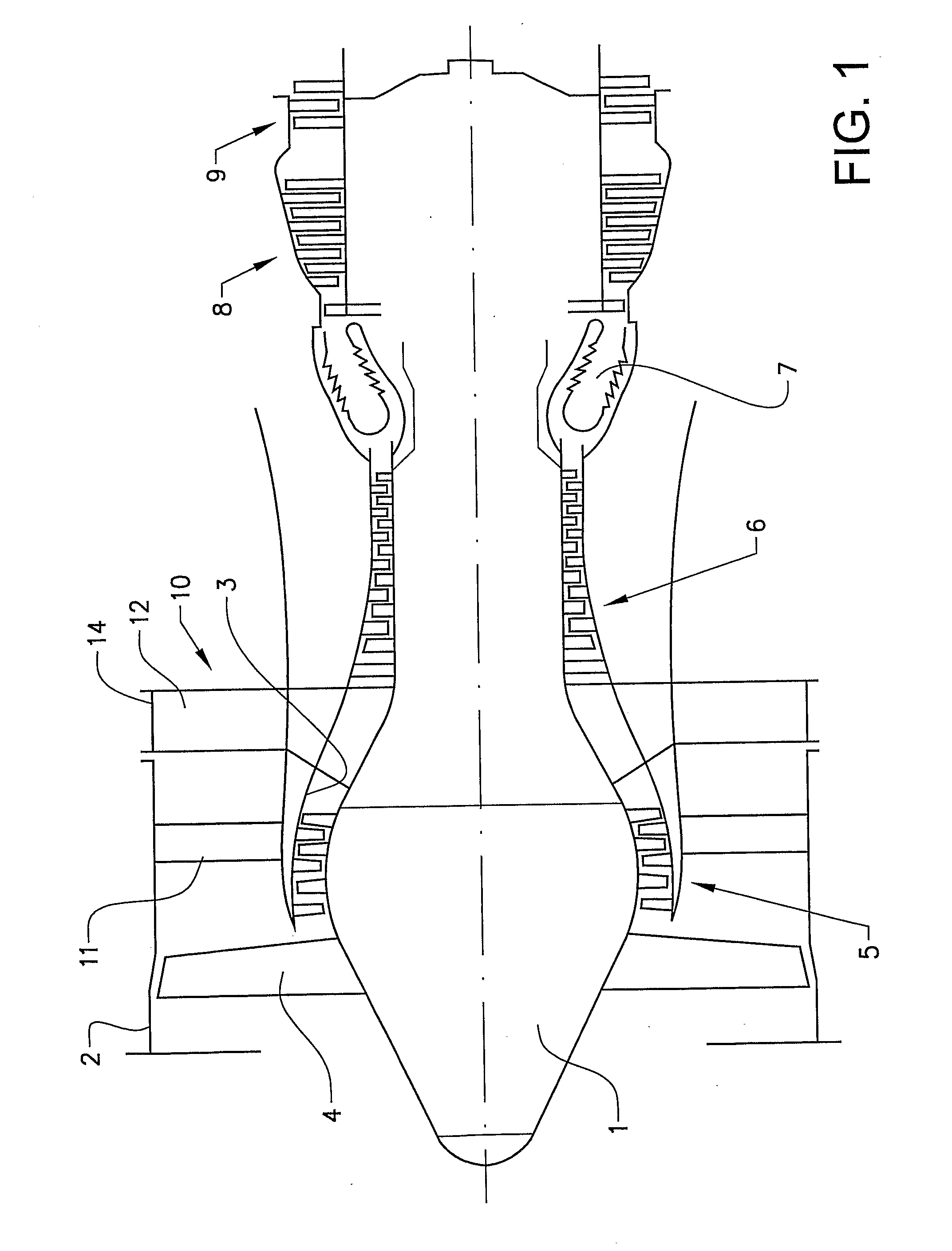
[0023]FIG. 1 shows a turbojet engine. The turbojet engine comprises a central body 1, an annular outer casing 2 (fan casing), an annular inner casing 3 (engine casing), a fan or blower 4, a low pressure compressor 5, a high pressure compressor 6, a combustion chamber 7, a high pressure turbine 8 and a low pressure turbine 9. It further comprises a set of arms 10 extending in a radial direction from the inner casing 3 to the outer casing 2. The arms 10 comprise aerodynamic vanes 11 primarily provided to act as guide vanes for air passing through the annular channel between the inner casing 3 and the outer casing 2 in an axial direction, i.e. a. longitudinal direction, of the engine. The arms 10 further comprise structural arms or load carrying vanes 12 primarily provided to guarantee a certain mechanical strength of the construction. Here, the aerodynamic vanes 11 and the load carrying vanes 12 are arranged in axially separated sets of arms. However, they could as well be arranged in...


PUM


Abstract

A component includes a first member, a second member and a device for fastening the first member to the second member. A first hole extends through a portion of the first member and a second hole extends through a portion of the second member. The first member and the second member are positioned such that the first hole and the second hole coincide. The fastening device includes an elongated fastening element arranged in the coinciding holes and a bushing arrangement arranged around the fastening element and adapted to establish a load transmission path between the first member and the second member. A first part of the bushing arrangement is arranged such that an inner surface thereof is positioned at a distance from an exterior surface of the fastening element for establishing a first load transmission path via the bushing arrangement and bypassing the fastening element in a first load condition. Further, the fastening device is adapted to allow the first member to move relative to the fastening element in a second load condition such that the first part of the bushing arrangement can be brought into contact with the fastening element for establishing a second load transmission path between the first member and the second member via the fastening element.

Description

BACKGROUND AND SUMMARY[0001]The present invention relates to a component comprising a first member, a second member and a device for fastening the first member to the second member, wherein a first hole extends through a portion of the first member and a second hole extends through a portion of the second member, wherein the first member and the second member are positioned such that the first hole and the second hole coincide, wherein the fastening device comprises an elongated fastening element arranged in said coinciding holes and a bushing arrangement arranged around the fastening element and adapted to establish a load transmission path between the first member and the second member.[0002]The inventive component is particularly suitable for application in a gas turbine engine. Especially, the gas turbine component is configured for a static application in the gas turbine engine. In such a gas turbine component, the first member forms a radially extending arm, or vane and the se...

Claims


Application Information

Patent Timeline
Patent Type & Authority Applications(United States)
IPC IPC(8): F16B33/00
CPCF01D5/30F01D9/042F05B2260/301Y02T50/672Y10T403/75F05D2300/603Y10T403/645Y10T403/453Y02T50/673F16B2200/506Y02T50/60
Inventor SAMUELSSON, RICKARDJANSSON, NIKLAS
Owner GKN AEROSPACE SWEDEN AB
Why Eureka
Try Eureka