Horizontal axis wind turbine apparatus

a horizontal axis wind turbine and nacelle technology, applied in mechanical equipment, machines/engines, endless-chain machines, etc., can solve the problems of increasing the manufacturing cost, maintenance and inspection of the damper, and the inability to control the size of the resistance torque for a certain input, so as to effectively suppress the yaw movement of the nacelle and effectively lessen the impact or vibration

Inactive Publication Date: 2011-12-08
HITACHI LTD
View PDF1 Cites 16 Cited by
  • Summary
  • Abstract
  • Description
  • Claims
  • Application Information

AI Technical Summary

Benefits of technology

[0009]Considering the above situation, the purpose of the present invention is to provide a horizontal axis wind turbine apparatus that is capable of effectively suppressing yaw movement of the nacelle as well as effectively lessening and absorbing impact or vibration by causing a resistance torque against the yaw movement of the nacelle according to the rate of change of the azimuth angle of the nacelle without adding special equipment to the basic construction of the horizontal axis wind turbine apparatus for applying a resistance torque to the yaw movement of the nacelle.
[0024]With the present invention, it is possible to effectively suppress yaw motion of the nacelle by suitably calculating and applying a resistance torque that acts against the yaw motion of the nacelle according to the rate of change of the azimuth angle of the nacelle. In other words, as a result, it is possible to effectively suppress a rapid change in the azimuth angle of the nacelle, and thus protect the rotor and the like by effectively lessening and absorbing impact and vibration.
[0025]Moreover, with the present invention, the rotor is used as a device that applies a resistance torque against yaw movement. Therefore, the invention has an advantage in that there is no need for special equipment for applying resistance torque against yaw motion of the nacelle to be added to the basic construction of a horizontal axis wind turbine. Therefore, it is possible to apply the invention at low cost to all kinds of independent pitch control type horizontal axis wind turbines, and thus the burden of maintaining and inspecting the mechanical elements is not increased.
[0026]Furthermore, the present invention has the advantage of being capable of setting and changing the setting of the resistance torque that is applied against yaw motion of the nacelle according to the rate of change of the azimuth angle of the nacelle without changing any of the mechanical elements.

Problems solved by technology

When performing operation in which there is the free yaw rotation of a horizontal axis wind turbine apparatus, a large gyro moment occurs in the rotor (blades, main shaft) or the like when the azimuth angle of the nacelle changes rapidly, which may cause damage to the rotor.
However, in the invention disclosed in Japanese Patent Publication No. 2007-198167, a rotary damper is necessary, which increases the manufacturing cost as well as maintenance and inspection of that damper.
Moreover, in the case of a rotary damper, the resistance torque that responds to the input is set according to the damper characteristics, so it is not possible to control the size of the resistance torque for a certain input.
The rotary damper is located near the axis of yaw rotation of the nacelle, so it is difficult to obtain large input.
Therefore, it is also difficult to obtain large resistance torque.
Therefore, there is a possibility that there will be a sudden change in the azimuth angle of the nacelle when the friction resistance exceeds the static friction force, and this technology does not have the characteristic of generating a larger resistance torque for faster changes in the azimuth angle of the nacelle, or that of generating a smaller resistance torque for slower changes in the azimuth angle of the nacelle.
Consequently, it is not possible to effectively suppress sudden changes in the azimuth angle of the nacelle, and to effectively lessen and absorb impact or vibration.

Method used


Image

  • Horizontal axis wind turbine apparatus
  • Horizontal axis wind turbine apparatus
  • Horizontal axis wind turbine apparatus

Examples


Embodiment Construction

[0035]In the following, an embodiment of the present invention will be explained with reference to the accompanying drawings. The following is just one embodiment of the present invention and does not limit the invention.

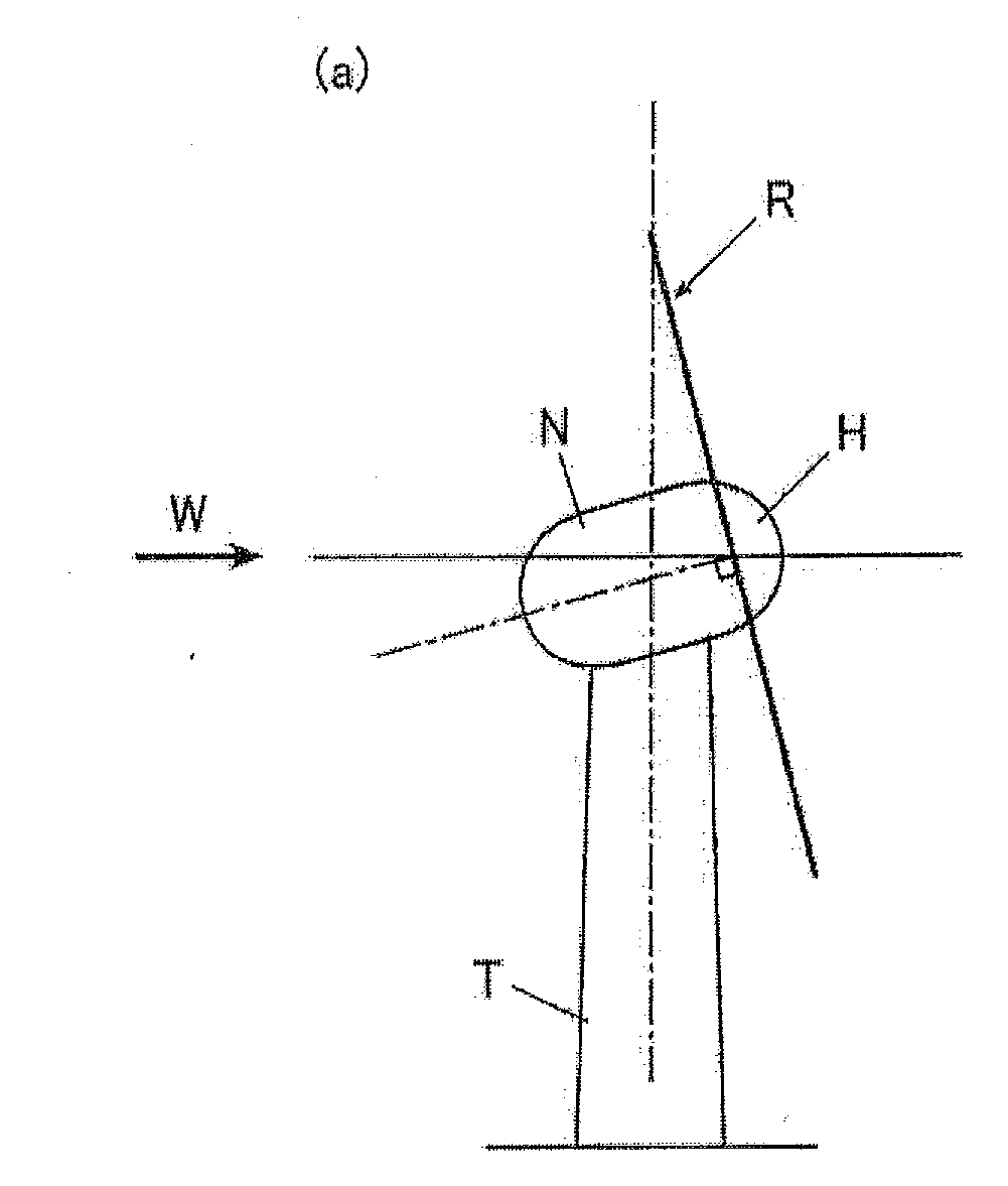
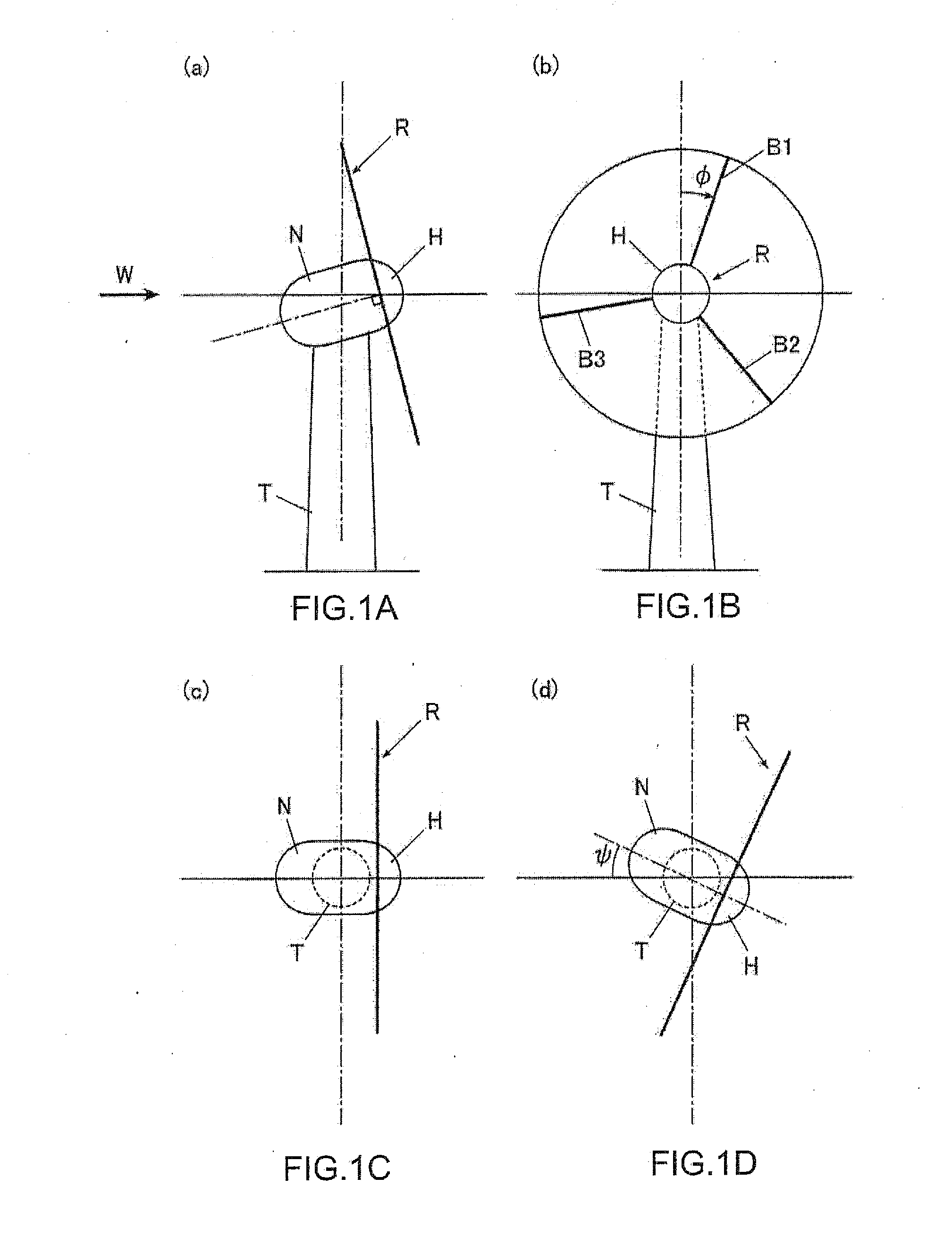
[0036]The horizontal axis wind turbine apparatus as illustrated in FIGS. 1A to 1D comprises a rotor R having a hub H to which blades B1, B2 and B3 are attached, a nacelle N that axially supports the rotor R via a main shaft such that it rotates freely, and a tower T that supports the nacelle N such that there is a free yaw rotation. This horizontal axis wind turbine is a downwind type horizontal axis wind turbine, and by the rotor R, which is located further downwind than the tower, receiving wind W, the rotor R rotates. As illustrated in FIG. 1B, φ is the azimuth angle of the rotor, and is the same as the azimuth angle of the blade B1. This horizontal axis wind turbine has three blades B1, B2 and B3. The blades B1, B2 and B3 each have an azimuth angle, however, the...


PUM


Abstract

The object of the invention is to provide a control apparatus C of a horizontal axis wind turbine apparatus WTG that calculates the value en of a pitch angle command for each blade based on the rate of change ΨD of the azimuth angle Ψ of a Nacelle N and the rotor azimuth angle φ of the blades B1, B2 and B3, causes the rotor to generate torque around the yaw axis by periodically controlling the angle change of the pitch angle of the blades, and using that torque, controls the rate of change of the azimuth angle of the nacelle. The value of that angle change is calculated as a value that increases as the inputted value of the rate of change ΨD increases.

Description

CROSS REFERENCE TO RELATED APPLICATIONS[0001]This application claims priority under 35 U.S.C. 119 based upon Japanese Patent Application Serial No. 2010-130582, filed on Jun. 8, 2010. The entire disclosure of the aforesaid application is incorporated herein by reference.FIELD OF THE INVENTION[0002]The present invention relates to yaw angle control of a horizontal-axis wind turbine apparatus.BACKGROUND OF THE INVENTION[0003]Typically, a horizontal-axis wind turbine apparatus comprises a rotor to which one, two or more blades are attached radially from a hub, a nacelle which rotatably supports the rotor by means of supporting a main shaft of the rotor which extends in the horizon and to which the hub is fixed, and a tower that supports the nacelle such that there is a free yaw rotation.[0004]When performing operation in which there is the free yaw rotation of a horizontal axis wind turbine apparatus, a large gyro moment occurs in the rotor (blades, main shaft) or the like when the azi...

Claims


Application Information

Patent Timeline
Patent Type & Authority Applications(United States)
IPC IPC(8): F03D7/04
CPCF03D7/0204F03D7/0224F03D7/024F05B2240/2213F05B2260/901F03D7/043F05B2270/329Y02E10/723F03D7/044F03D7/042F03D7/0212F05B2270/326Y02E10/72
Inventor YOSHIDA, SHIGEO
Owner HITACHI LTD
Why Eureka
Try Eureka