
Universal joint assembly for an automotive driveline system

Inactive Publication Date: 2011-12-08
RONJO
View PDF5 Cites 23 Cited by
  • Summary
  • Abstract
  • Description
  • Claims
  • Application Information

AI Technical Summary

Benefits of technology

[0018]An advantage of the present invention is to provide an improved yoke portion for a universal joint that may be stamped from a sheet metal presenting a light weight alternative to an iron cast yoke portion for an automotive driveline assembly axis known in the prior art, which reduces the effect of vibrations and the resulting noises.
[0019]Another advantage of the present invention is to provide an improved yoke portion that reduces the mass of the improved yoke portion thereby making it easier to balance and increase performance of the driveline applications at a low cost and a high volume.
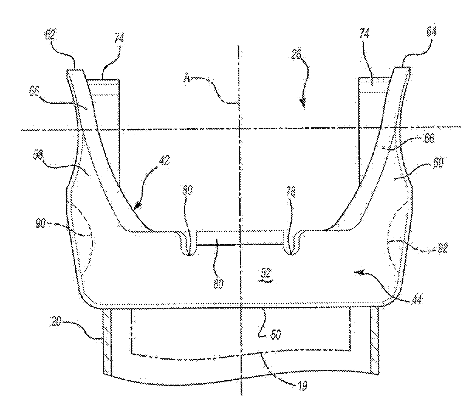
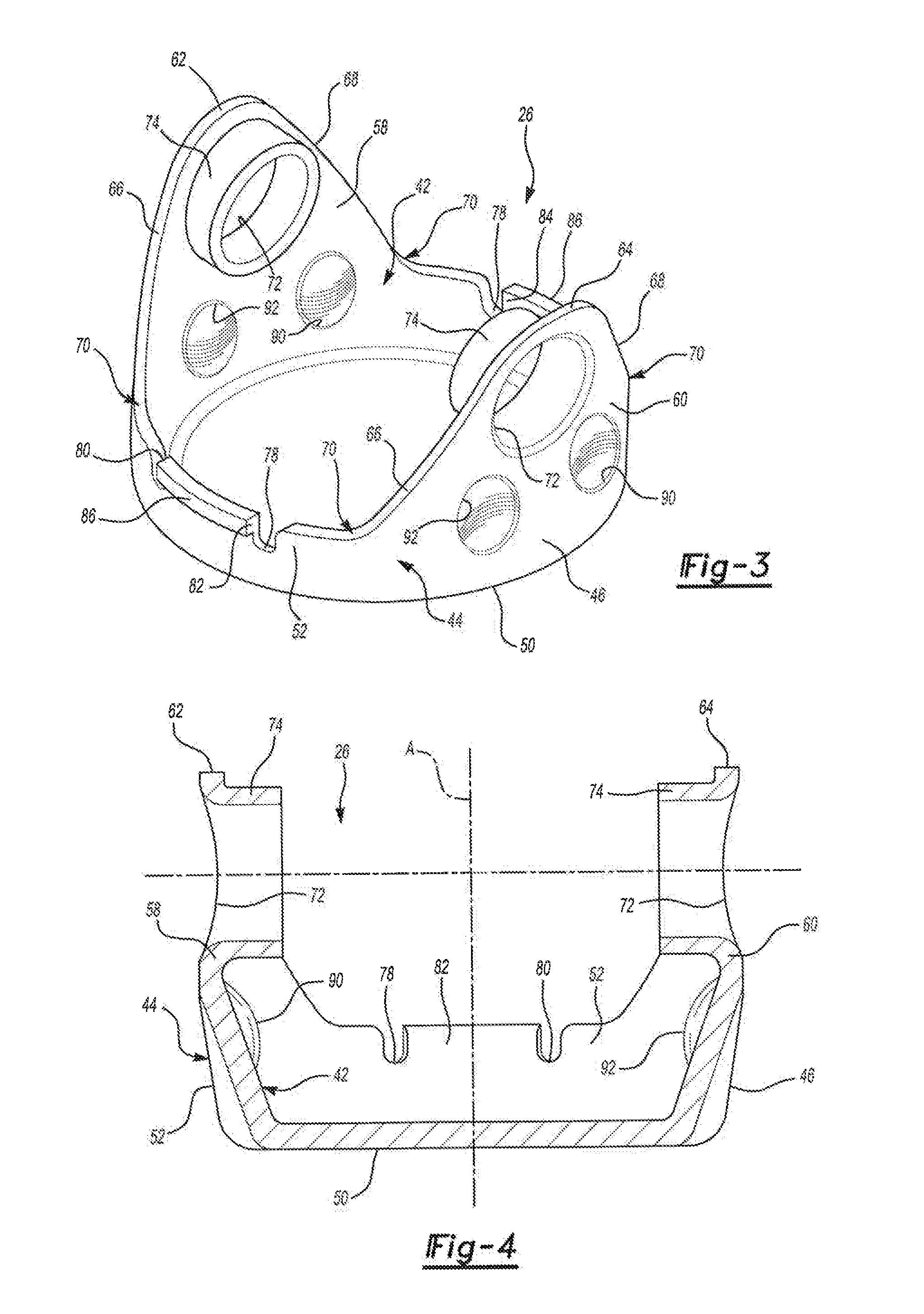
[0020]Still another advantage of the present invention is to provide an improved yoke portion wherein each spaced lug presents a central axis which may have sloping side walls inclined from the head to the neck thereby reducing stress applied to the yoke portion and preventing the spaced lugs from bending as the yoke portion rotates around the longitudinal axis.

Problems solved by technology

In addition, the yoke does not include reinforcing features of any kind to prevent bending of the arm portions during rotation of the yoke.
Typical prior art yoke portions are iron cast to provide durability but are difficult to balance.
As will be understood by those skilled in this art, however, any misalignment of these several components of this yoke assembly will result in vibration or the components may become misaligned following assembly.
Further, this yoke assembly is relatively expensive, particularly when compared with the improved universal joint of this invention.
However, the disclosed fork would not be suitable for the universal joint of an automotive driveline assembly subject to high torsional loads.

Method used


Image

  • Universal joint assembly for an automotive driveline system
  • Universal joint assembly for an automotive driveline system
  • Universal joint assembly for an automotive driveline system

Examples


Embodiment Construction

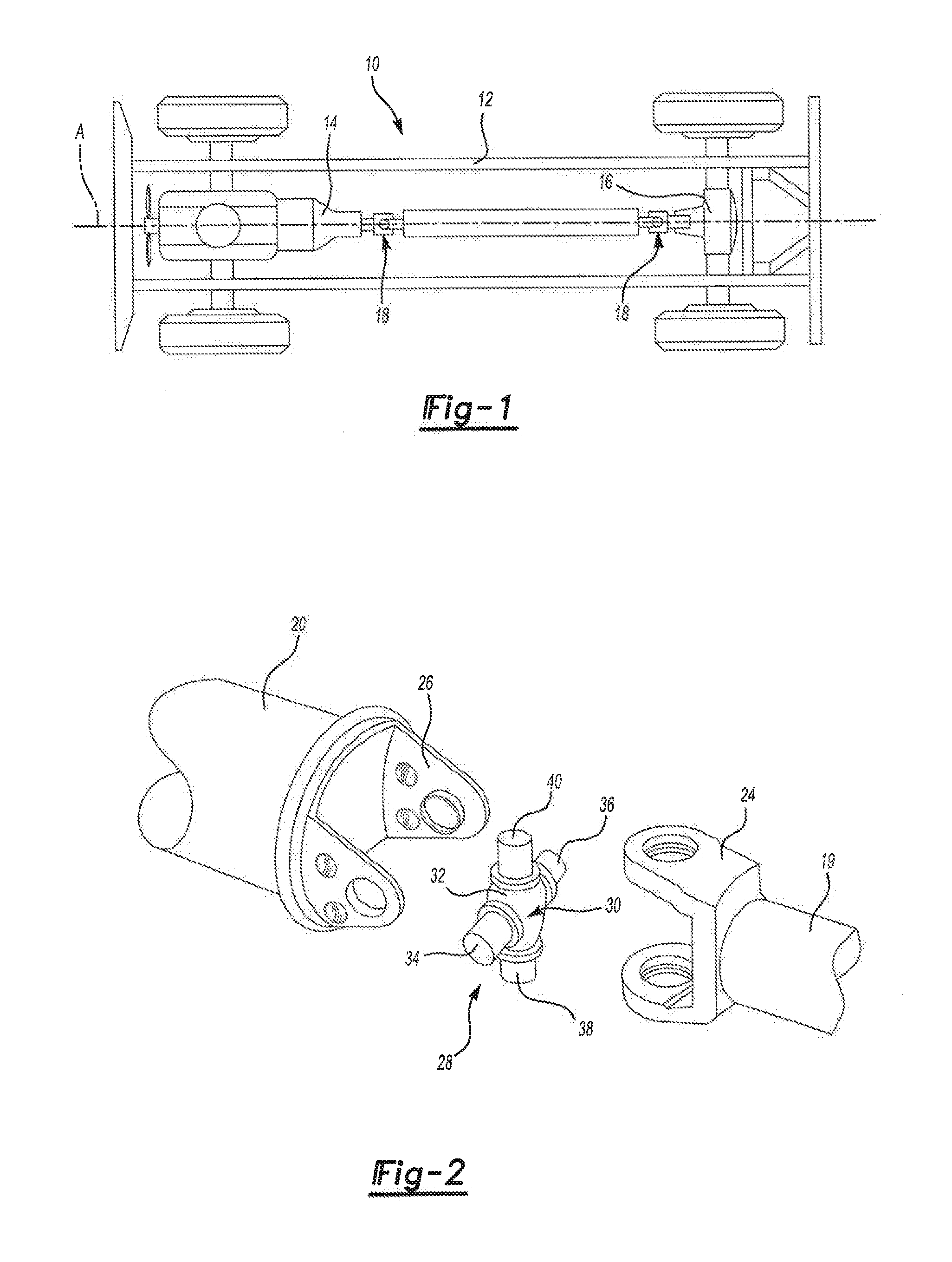
[0041]Referring to FIG. 1, a chassis of an automotive vehicle, generally shown at 10, includes a frame 12 and a driveline mechanism. The driveline mechanism includes a transmission assembly 14, a differential assembly 16, and two universal joints, generally indicated at 18, extending between the transmission assembly 14 and the differential assembly 16 presenting an operative communication therebetween. The universal joint 18 rotates around a longitudinal axis A during its operational mode. The universal joint 18, as better illustrated in FIG. 2, includes a first drive shaft 19 and a second drive shaft 20 with a pair of yokes, such as, for example a first yoke 24 and a second yoke 26. The first yoke 24 is attached to the first drive shaft 19 and the second yoke or yoke portion 26 is attached to the second drive shaft 20.

[0042]A connector or cruciform assembly, generally shown at 28, interconnects the first yoke 24 and the second yoke 26. The cruciform assembly 28 includes a cross me...


PUM


Abstract

A die formed monolithic yoke assembly for a universal joint of an automotive driveline assembly subject to high torsional loads having a substantially uniformed thickness, including a cup-shaped portion, a pair of opposed lugs integral with and extending from an upper portion of the cup-shaped portion and an integral, outwardly deformed substantially continuous lip portion extending outwardly from the upper surface of the annular wall and the lugs substantially strengthening the yoke assembly particularly against torsional loads. In one embodiment, the upper end of the cup-shaped portion included concave arcuate portions on opposed sides of the lugs adjacent the lugs, such that the upper surface of the cup-shaped portion transitions from a concave surface to a convex surface strengthening the yoke.

Description

RELATED APPLICATIONS[0001]This application is a continuation in part application of U.S. patent application Ser. No. 11 / 939,031 for a UNIVERSAL JOINT ASSEMBLY FOR AN AUTOMOTIVE DRIVELINE SYSTEM, filed on Nov. 13, 2007, which claims priority to U.S. application Ser. No. 11 / 262,622 for a UNIVERSAL JOINT ASSEMBLY FOR AN AUTOMOTIVE DRIVELINE SYSTEM, filed on Oct. 31, 2005, now U.S. Pat. No. 7,320,645, which claims priority to U.S. Patent Application No. 60 / 636,190 for a UNIVERSAL JOINT ASSEMBLY FOR AN AUTOMOTIVE DRIVELINE SYSTEM, filed on Dec. 15, 2004 which application claimed the benefit of the provisional patent application Ser. No. 60 / 623,674 for a VEHICLE HAVING A UNIVERSAL JOINT DEVICE AND A PROCESS OF MAKING THE SAME, filed on Oct. 29, 2004 and, which are hereby incorporated by reference in their entireties.BACKGROUND OF THE INVENTION[0002]1. Field of the Invention[0003]The subject invention relates generally to a driveline system for a vehicle transmission. More particularly, th...

Claims


Application Information

Patent Timeline
IPC IPC(8): F16D3/16
CPCF16D3/387F16D3/40
Inventor SZUBA, JOSEPHFRADKIN, HENRYKUCINSKI, ROBERT D.
Owner RONJO
Learn More