Power and pin efficient chip-to-chip communications with common-mode rejection and sso resilience

a chip-to-chip communication and common-mode rejection technology, applied in the field of communication, can solve problems such as limiting the speed of the communication bus, generating electrical noise, errors,

Active Publication Date: 2011-12-08
ECOLE POLYTECHNIQUE FEDERALE DE LAUSANNE (EPFL)
View PDF4 Cites 191 Cited by
  • Summary
  • Abstract
  • Description
  • Claims
  • Application Information

AI Technical Summary

Problems solved by technology

As is well known, the communication requires electrical energy and can generate electrical noise and errors can occur when the conditions of communication are not ideal.
For an increasing number of applications, the speed of the communication bus is a limiting factor.
However, this also increases the number of pins of the ICs that are needed and many times, IC pins are a scarce resource.
Another limiting factor is the power consumption of the bus and the circuitry driving the bus.
Simply increasing the transmit power might not result in a better performance of the bus, because that might increase the amount of noise and lower performance.
Signals transmitted on a communication bus are subjected to several types of noise.
Another type of noise is interference that may result from neighboring wires of the communication bus.
Some noise and interference has a component that is common to the several wires of the bus and this noise is called common-mode noise.
Another source of noise is simultaneous switching output (“SSO”) noise that is caused by a bus driver current that varies in time.
SSO noise can cause major problems in modern high-speed bus communication systems.
Yet another source of noise is crosstalk noise, which is caused by interference of the signals on the different wires of the same bus.
Crosstalk noise is one of the main sources of noise for high-frequency buses and is hard to eliminate by just increasing the energy of the signals on the bus, since an increase of energy leads directly to an increase of interference to nearby wires on the bus, and will lead to even worse crosstalk noise.
Although single-ended signaling is efficient in terms of the number of wires used, it is susceptible to common-mode noise and it introduces SSO noise.
Inaccuracies in the generation of the reference signal lead to higher error rates of the communication system.
Single-ended signaling is also not very efficient in terms of transmission power that is required to achieve certain Gaussian noise resilience, and it is also not efficient in terms of crosstalk noise.
The main disadvantage of differential signaling is that it uses twice the number of pins compared to differential signaling.
While communication buses based on differential signaling provide good noise resilience, their pin efficiency is low.
Differential signaling is more power efficient than single-ended signaling but still a substantial amount of the power consumption of a bus communication system is used in the drivers of the bus wires.
With the methods of Cronie II, improving the noise resilience of the system might use up a significant number of pins saved by ODVS and the circuitry needed for encoding and decoding according to the teachings of Cronie II may be complex and may not be applicable in situations where the data transfer is of very high rate, thus requiring another approach.

Method used


Image

  • Power and pin efficient chip-to-chip communications with common-mode rejection and sso resilience
  • Power and pin efficient chip-to-chip communications with common-mode rejection and sso resilience
  • Power and pin efficient chip-to-chip communications with common-mode rejection and sso resilience

Examples


example vector

Signal Encoder

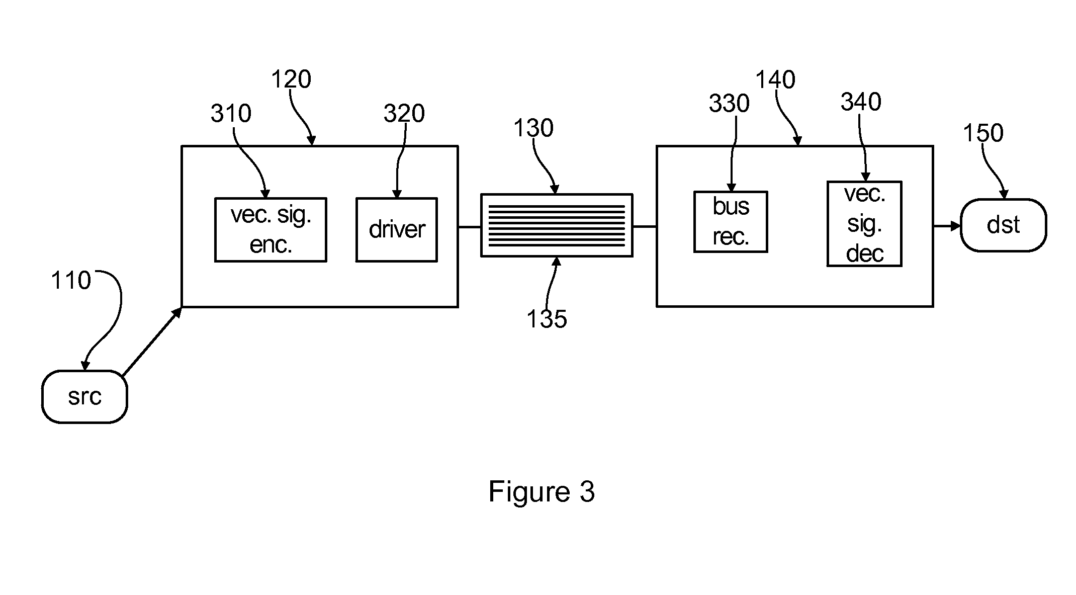
[0062]FIG. 3 is a schematic diagram illustrating use of a vector signal encoder and a vector signal decoder. Bus transmitter 120 might include a vector signal encoder 310 and a bus driver 320, while bus receiver 140 might include a vector signal decoder 340 and a bus receiver 330. Vector signal encoder 310 preferably encodes the information provided by source 110 such that Equations 1 and 2 hold.

[0063]In one example, vector signal encoder 310 uses a form of vector pulse amplitude modulation, wherein a basic pulse shape, p(t), with a finite duration of T seconds is defined and the amplitude of this pulse is modulated according to a signaling scheme. Two examples of pulse shapes are shown in FIG. 4. The left hand-side of FIG. 4 shows a rectangular pulse 410 of duration T. Pulse 410 is often used as an approximation for modeling purposes. A more practical pulse 420 is shown in the right hand-side of FIG. 4. Pulse 420 has a finite rise time, tr. In one preferred embodiment...


PUM


Abstract

In bus communications methods and apparatus, a first set of physical signals representing the information to be conveyed over the bus is provided, and mapped to a codeword of a spherical code, wherein a codeword is representable as a vector of a plurality of components and the bus uses at least as many signal lines as components of the vector that are used, mapping the codeword to a second set of physical signals, wherein components of the second set of physical signals can have values from a set of component values having at least three distinct values for at least one component, and providing the second set of physical signals for transmission over the data bus in a physical form.

Description

CROSS REFERENCES[0001]The following prior applications are herein incorporated by reference in their entirety for all purposes:[0002]U.S. patent application Ser. No. 12 / 784,414 filed May 20, 2010 naming Harm Cronie and Amin Shokrollahi and entitled “Orthogonal Differential Vector Signaling” (referred to herein as “Cronie I”); and[0003]U.S. Provisional Patent Application No. 61 / 351,845 filed Jun. 4, 2010 naming Harm Cronie and Amin Shokrollahi entitled “Error Control Coding for Differential Signaling” (referred to herein as “Cronie II”).[0004]The following references are cited in this application using the labels set out in brackets:[0005][Slepian] Slepian, D., “Permutation Modulation”, Proceedings of the IEEE, Vol. 53, No. 3, pp. 228-236 (March 1965);[0006][Cornelius] U.S. Pat. No. 6,661,355 to William Cornelius and William Althas entitled “Methods and Apparatus for Constant-Weight Encoding & Decoding” (2003);[0007][Stan-Burelson] Stan, M., and Burelson, W., “Bus-Invert Coding for L...

Claims


Application Information

Patent Timeline
Patent Type & Authority Applications(United States)
IPC IPC(8): H03M13/19H04L27/00
CPCH03M5/04H03M5/16H04L2001/0094H04L1/0041H04L1/0057H03M13/31
Inventor CRONIE, HARMSHOKROLLAHI, AMIN
Owner ECOLE POLYTECHNIQUE FEDERALE DE LAUSANNE (EPFL)
Why Eureka
Try Eureka