Structure for rigidly connecting solar panels to a fixture

a technology for solar panels and fixtures, applied in the field of solar panels, can solve the problems of increasing overall costs, reducing the service life of solar panels, and not ensuring sealing, so as to achieve the effect of enhancing protective properties

Inactive Publication Date: 2011-12-15
INSTITUT DE RECH FONDAMENTALE & TECH SOLAIRES - IRFTS
View PDF75 Cites 74 Cited by
  • Summary
  • Abstract
  • Description
  • Claims
  • Application Information

AI Technical Summary

Benefits of technology

[0022]Put another way, the inventive rigid connection structure comes in the form of a frame, and in particular a frame cast in one piece, free from any material at its center, and therefore hollow, of standardized dimensions complementary to the standardized dimensions of the solar panels or modules, the frame being intended to be secured directly to a fixture. This frame is capable in particular of accommodating the lateral selvages of a solar panel, and it is fitted with chutes or projecting elements arranged so as to reduce water infiltration into the building. Each of the longitudinal edges of the frame includes in particular an internal chute connected to an external chute by means of a support surface. The internal chute is intended in particular to be positioned opposite the lower face of the panel, and is additionally intended for condensate recovery. The external chute is intended in particular for rainwater runoff.
[0024]According to the invention, the frame defines a continuous or single piece chute, in other words provides a continuity between the chutes oriented perpendicular to the direction of the rake and the chutes oriented in the direction of the rake. This helps to drain away the runoff water, and consequently to seal the assembly.
[0026]This capacity for covering the longitudinal sections of adjacent frames, both in the transverse or lateral direction and in the direction of the pitch, means that the seal can be provided without necessarily using connection couplings. This represents a significant factor in terms of saving time during installation, and consequently in terms of reducing the associated costs.
[0029]For example, the means for securing the frame to the fixture include a set of screws capable of cooperating with through orifices or machined bores implemented in the wall forming the bottom of each of the internal longitudinal chutes. Securing the frame on the internal chute guarantees a better seal to the roofing, since also, said internal chutes are not intended for the collection of runoff water (rain or snow), since they are located under the panels, and not at the junction of two adjacent panels. Incidentally, they are separated from the external chutes by a projection, guaranteeing them from any intrusion of runoff water and rainwater.
[0030]According to one inventive embodiment, the tightening means may include at least one tangent plate cooperating with at least one screw and one securing lug to prevent the longitudinal selvage of the panel from lifting when said selvage is trapped, the tangent plate being intended to be rigidly connected to a portion of one of the longitudinal sections defining the frames.
[0039]According to one inventive embodiment, the edge of the first transverse chute connected to the first support surface forms an upward projecting chevron structure and is capable of preventing any sliding, in the direction of the pitch, of the upper selvage of the panel.

Problems solved by technology

One of the difficulties encountered lies in the area of the seal.
However, the actual panels are themselves secured to sections that are rigidly connected to the framework, for example, using screws or nails that pass through and therefore perforate said membrane, so that the seal is not guaranteed.
Incidentally, this solution compels the prior installation of said membrane, thereby inducing further down time, raising the overall costs.
These continuous high voltages mean that significant precautions have to be taken, and in particular the use of specialized cabling and connections.
They carry a risk when it comes to technicians or members of the emergency services working on roofs that include said solar modules.
Indeed, even if a fire breaks out, the solar modules are still able to deliver high voltages which may entail risks of electrocution for members of the emergency services such as firemen for example.
This solution does work in practice, but forms a heavy block that is difficult to integrate.
Additionally, because of this securing mode, a hot point is created in the module, that may affect the yield thereof.
A problem arises from the prior art related to the integration of these inverters into the solar assembly, as part of a roof integration facility.
There is then a problem with providing the integration device with standardized flashings that can be fitted to all types of roofing.
Apart from the costs generated by the labor deployed in this way, the costs are raised because specialized components have to be manufactured.

Method used


Image

  • Structure for rigidly connecting solar panels to a fixture
  • Structure for rigidly connecting solar panels to a fixture
  • Structure for rigidly connecting solar panels to a fixture

Examples


Embodiment Construction

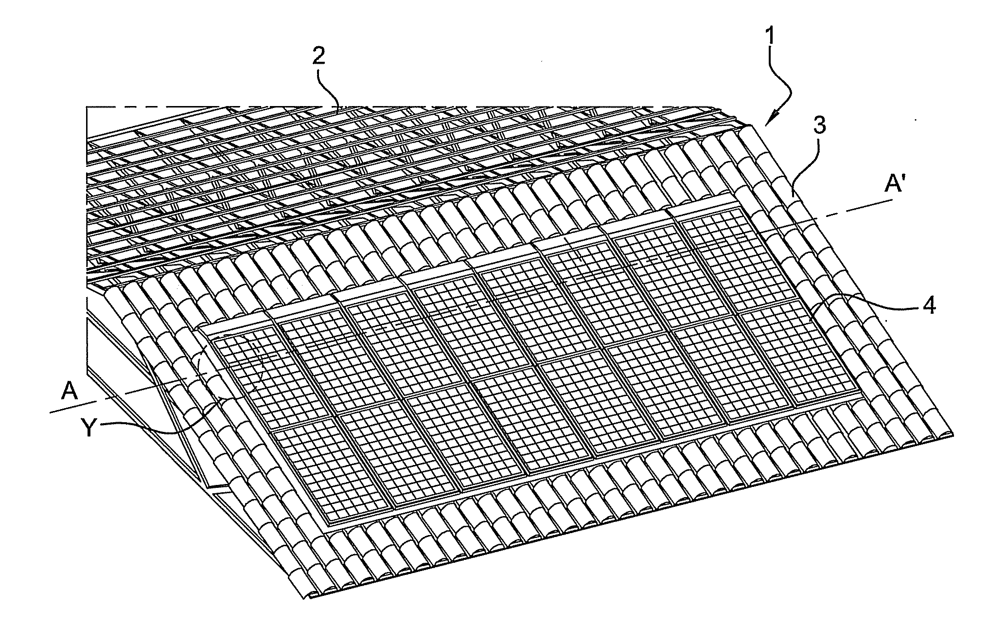
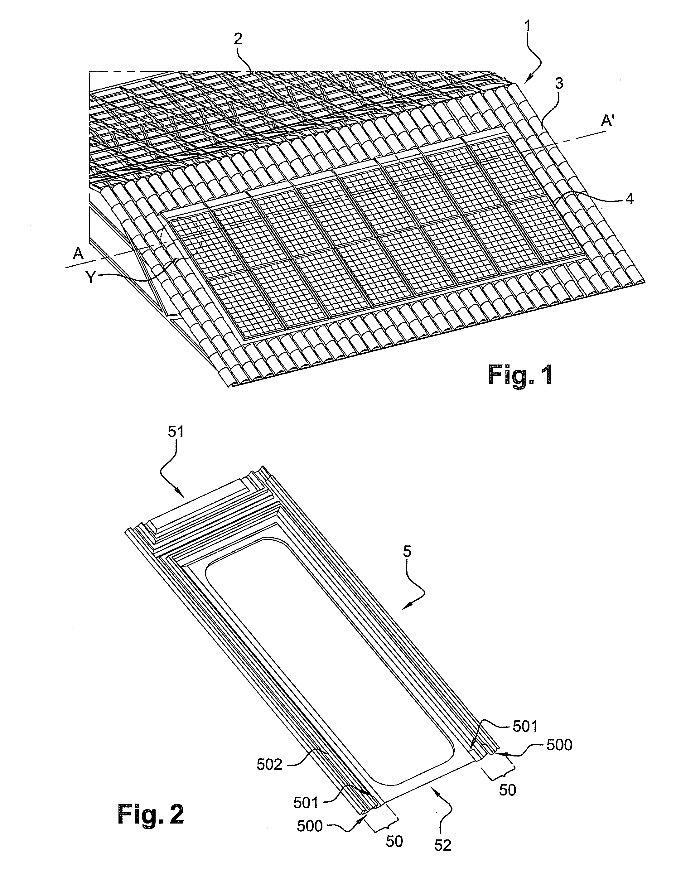
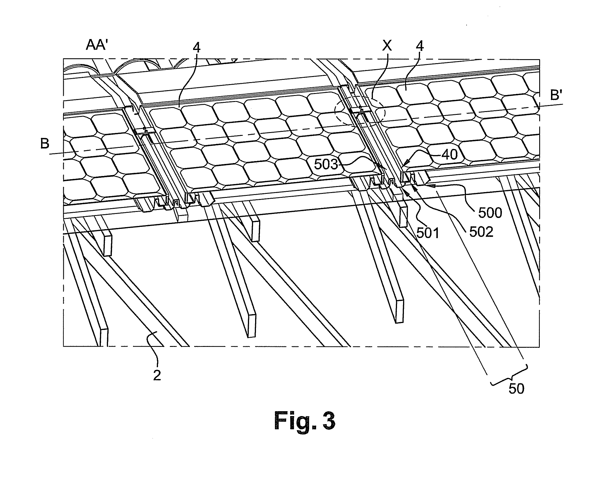
[0074]FIG. 1 shows diagrammatically a portion of a roof covering 1 secured directly to a fixture 2, constituted in the case in point by a wooden roofing framework. The covering 1 comprises in particular tiles 3 and solar panels 4. It may be seen that these panels are integrated into said roofing, in the sense that they help to seal it.

[0075]A panel or solar module 4 commonly comes in the form of a set of photovoltaic cells surrounded by an aluminum frame. Each of the solar modules 4 is secured directly to the fixture by means of a structure or rigid connection device.

[0076]The rigid connection structure includes in particular a plurality of frames, in the case in point one frame per solar panel, on which the selvages or edges of said panel rest, tightening means capable of holding the panel selvages on the frame, and means for securing the frame to the fixture.

[0077]The frame 5, shown in FIG. 2, is formed in particular by at least two longitudinal sections 50 intended to be arranged...


PUM


Abstract

A device for integrating solar panels on a fixture, in particular a roofing framework, that includes a plurality of frames intended to accommodate the solar panels, added to the fixture, said frames being defined by a peripheral edge fitted with linear elements that project relative to the plane in which the frames are set; tightening means for holding said panels on the frames; and means for securing the frames to the fixture. The frames are openwork and cover or partially overlap each other on the edges which define them, laterally on the one hand and in the direction of the roof pitch on the other hand, the projecting linear elements with which they are fitted cooperating with each other to form a barrier seal.

Description

TECHNICAL FIELD[0001]This invention relates to the field of solar panels of the Building Integrated Photovoltaics (BIPV) type, namely solar panel systems in which the photovoltaic element, in addition to providing the electricity generation function, acts as one of the structural members, such as the roof for example.PRIOR ART[0002]Among the incentives initiated by the authorities, and especially the French authorities, to promote the development of non-fossil energy sources, is the concept of integration under which solar panels are given an actual protection and sealing function in the building to which they are added.[0003]In fact, many technological solutions have been developed in order, on the one hand, to secure said solar panels to roofs, and on the other hand, to meet the specifications laid down by government in relation to this concept of integration.[0004]One of the difficulties encountered lies in the area of the seal. To this end, a technical solution has been proposed...

Claims


Application Information

Patent Timeline
Patent Type & Authority Applications(United States)
IPC IPC(8): E04D13/18
CPCF24J2/4614F24J2/5207F24J2/5245F24J2/5256H02S20/23Y02B10/20Y02E10/47H02S40/32Y02B10/12F24S25/61F24S25/35F24S40/44F24S25/634Y02E10/50Y02B10/10
Inventor CRASNIANSKI, SERGE
Owner INSTITUT DE RECH FONDAMENTALE & TECH SOLAIRES - IRFTS
Why Eureka
Try Eureka