Flow rate control valve

a flow rate control and valve body technology, applied in the direction of mechanical equipment, machines/engines, transportation and packaging, etc., can solve the problems of affecting the flow rate of hydraulic fluid supply/discharge, and affecting the flow rate of hydraulic fluid supply

Inactive Publication Date: 2011-12-15
TOYOTA JIDOSHA KK
View PDF1 Cites 21 Cited by
  • Summary
  • Abstract
  • Description
  • Claims
  • Application Information

AI Technical Summary

Benefits of technology

[0017]According to the aspect of the invention, when the sleeve is assembled into the bolt, the phase of rotation of the sleeve with respect to the bolt is adjusted by the phase adjustment portion. When the phase of the sleeve is thus adjusted, the port coincides in position with the through hole and is unlikely to be blocked by that region of the sleeve which is not provided with the through hole. Accordingly, the oil passages for supplying / discharging the hydraulic fluid communicate with the accommodation chamber in the sleeve through the port and the through hole, so that a flow rate required for the supply / discharge of the hydraulic fluid is ensured.
[0032]In this manner, the sleeve is not assembled into the bolt with the corresponding ports of the sleeve and the bolt deviant from each other in the circumferential direction. Further, the sleeve assembled into the bolt does not rotate with respect to the bolt due to vibrations or the like from the internal combustion engine to cause the port of the sleeve to deviate from the port of the bolt in the circumferential direction. Thus, the flow rate required for the supply / discharge of the hydraulic fluid can be ensured.

Problems solved by technology

However, if the bolt is screwed to the camshaft to fix the movable member to the camshaft, the bolt may become distorted by a fastening torque as a result of a manufacturing error of the movable member, an assembly error of the movable member, manufacturing errors of the bolt and the camshaft, or the like.
Distortions of the bolt may result in a great dispersion of the gap between the bolt and the spool in some locations, thereby altering the flow rate characteristic of the flow rate control valve or cause an operational failure in the spool.
Then, if the respective ports are closed due to this distortion, it is difficult to ensure a flow rate required for the supply / discharge of the hydraulic fluid.

Method used


Image

  • Flow rate control valve
  • Flow rate control valve
  • Flow rate control valve

Examples


first embodiment

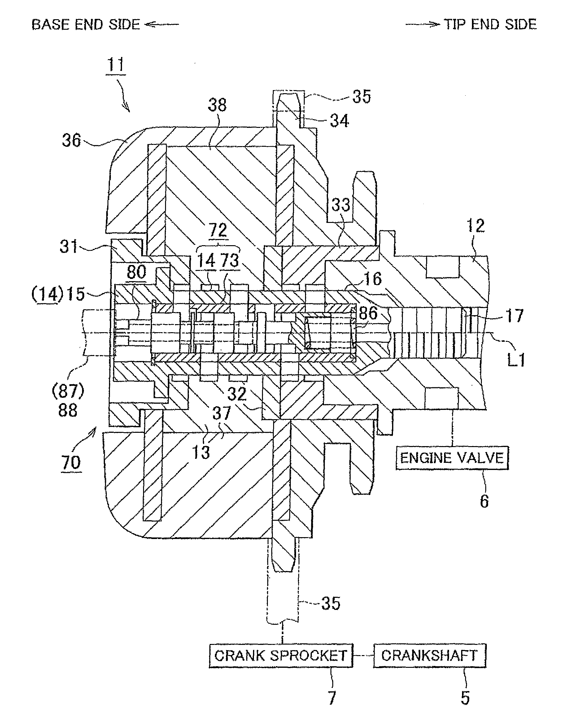
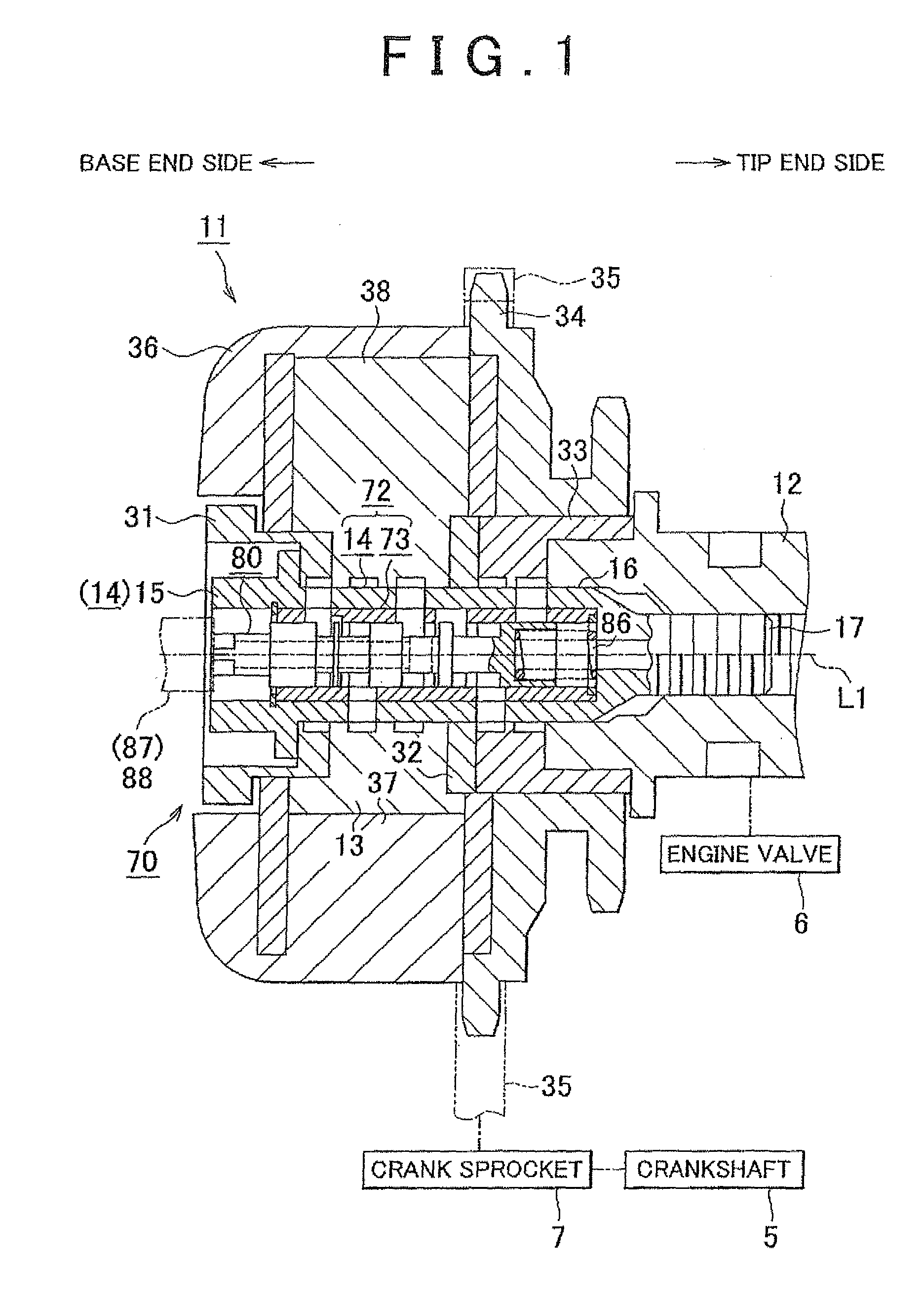
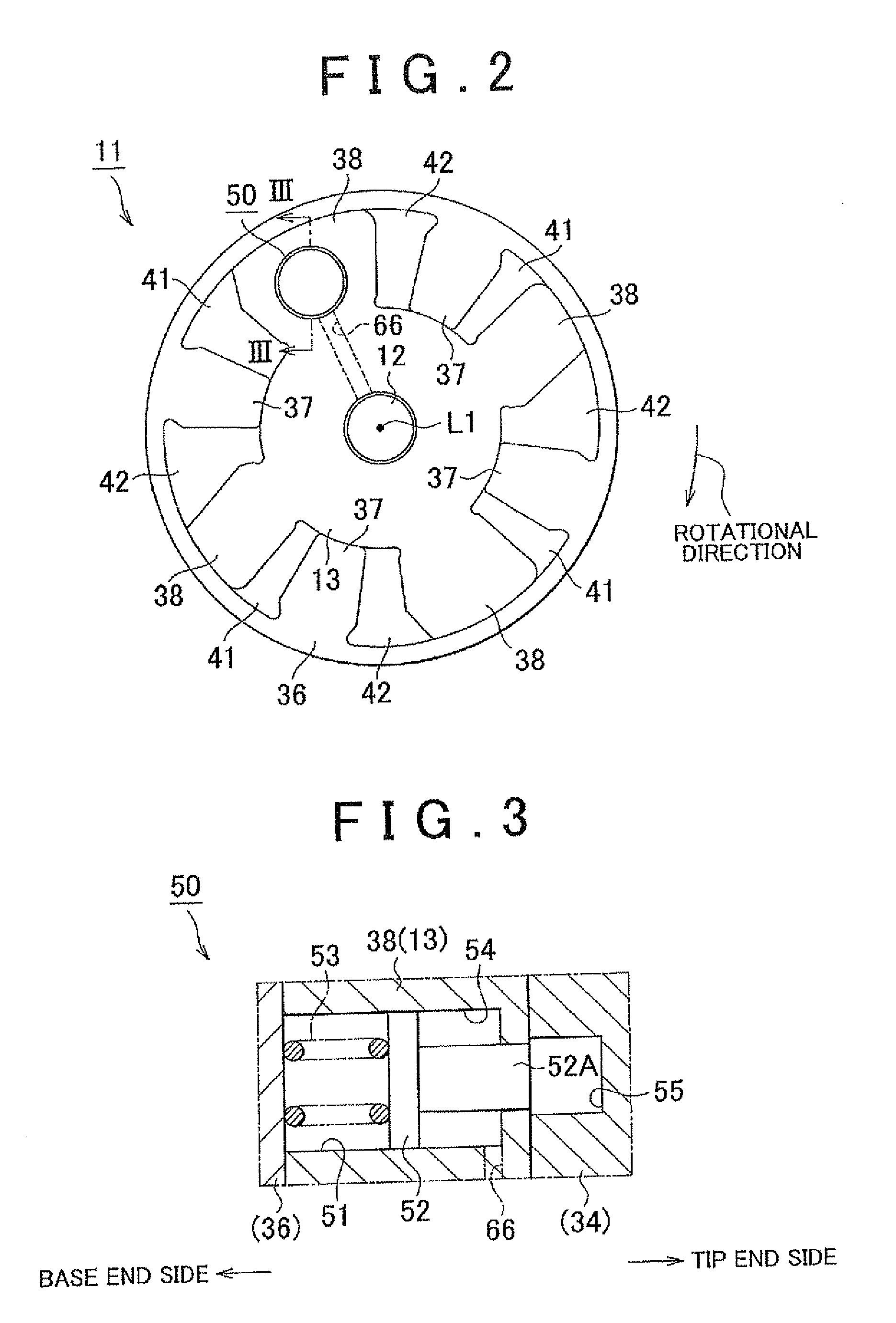
[0047]the invention will be described hereinafter with reference to FIGS. 1 to 11. As shown in FIG. 1, an internal combustion engine includes a crankshaft 5, which serves as an output shaft thereof, and a camshaft 12 that actuates the engine valves 6 such as intake valves and exhaust valves in an opening / closing manner. The crankshaft 5 and the camshaft 12 are rotatably supported in the direction indicated by the arrow of FIG. 2.

[0048]As shown in at least one of FIGS. 1 and 2, the internal combustion engine is equipped with a variable valve timing mechanism 11. The variable valve timing mechanism 11 changes the rotational phase of the camshaft 12 relative to the crankshaft 5 to vary the valve timing, that is, one of valve opening / closing characteristics of the engine valves 6. The expression to vary the valve timing means that the valve timing may be advanced or retarded while maintaining the duration (i.e., the valve open period) of the engine valves 6 constant.

[0049]The left side ...

second embodiment

[0107]Consequently, according to the invention, the following effects are obtained as well as the aforementioned effects (1) to (6). (7) A sleeve formed of a material having a higher coefficient of thermal expansion than the bolt 14 is employed as the sleeve 73. Thus, in the normal operating temperature range of the flow rate control valve 70 in which the temperature of the hydraulic fluid is high, the gap between the sleeve 73 and the bolt 14 is kept as narrow as possible to restrain the hydraulic fluid from leaking out and suppress the deterioration in the flow rate characteristic of the flow rate control valve 70.

[0108]Next, a third embodiment of the invention as still another concrete form thereof will be described. In the third embodiment of the invention, the material used to form the sleeve 73 has a coefficient of thermal expansion equal to or close to that of the bolt 14, but is otherwise configured identically to the first embodiment. In the embodiment, the sleeve 73 is for...

third embodiment

[0110]Further, the sleeve 73 press-fitted in the insertion portion 18 is unlikely to move in either the axial or circumferential directions. Thus, according to the invention, the following effects are obtained as well as the foregoing effects (1) to (6).

[0111]The sleeve 73 formed of the same material as the bolt 14 is press-fitted into the insertion portion 18 after the movable member 13 is fastened by the bolt 14. Thus, even if the bolt 14 is distorted by the fastening torque in fastening the movable member 13, the foregoing effect (1) of suppressing the change in the flow rate characteristic resulting from the gap between the sleeve 73 and the spool 80 and the operational failure in the spool 80 can be obtained.

[0112]Further, movement of the sleeve 73 in the direction along the axis L1 during the operation or the like of the flow rate control valve 70, which causes the positional relationships between the ports 22 to 26 and the through holes 74 to deviate or causes the positional ...


PUM


Abstract

A flow rate control valve includes a housing having an accommodation chamber in communication with oil passages, and a spool accommodated in the accommodation chamber movably in a reciprocating manner. The housing includes a bolt for fastening a movable member of a variable valve timing mechanism, and a sleeve inserted in an insertion portion provided in the bolt and having the accommodation chamber. The bolt is provided with a port through which the oil passages communicate with the insertion portion. The sleeve is provided with a through hole penetrating the sleeve. Furthermore, an annular protrusion and a recess are provided as a phase adjustment portion that adjusts a phase of rotation of the sleeve with respect to the bolt to a phase in which the port coincides in position with the through hole and holds the phase of rotation of the sleeve with respect to the bolt equal thereto.

Description

INCORPORATION BY REFERENCE[0001]The disclosure of Japanese Patent Application No. 2010432084 filed on Jun. 9, 2010 including the specification, drawings and abstract is incorporated herein by reference in its entirety.BACKGROUND OF THE INVENTION[0002]1. Field of the Invention[0003]The invention relates to a flow rate control valve provided in an internal combustion engine equipped with a variable mechanism, which operates a movable member in accordance with the supply / discharge of a hydraulic fluid and thus makes a valve opening / closing characteristic of an engine valve variable, to control the valve opening / closing characteristic.[0004]2. Description of Related Art[0005]Generally, many internal combustion engines are equipped with a variable valve timing mechanism that varies the timing of the engine valves such as intake valves and exhaust valves to improve fuel economy, enhance output, and the like. In such internal combustion engines, a movable member of the variable valve timin...

Claims


Application Information

Patent Timeline
Patent Type & Authority Applications(United States)
IPC IPC(8): F01L1/344F16K5/08
CPCF01L1/3442F01L2001/3443F01L2001/34433F01L2001/34469F01L2250/02Y10T137/86702F01L2301/00
Inventor NAKAMURA, KIYOHARUYOKOTA, JYUNJI
Owner TOYOTA JIDOSHA KK
Why Eureka
Try Eureka