Thermal diffuser and cooling apparatus for cooling heat source using the same
Inactive Publication Date: 2011-12-15
DENSO CORP +1
2 Cites 33 Cited by
AI-Extracted Technical Summary
Problems solved by technology
As a result, the improved thermal conductivity is still very low compared wit...
Abstract
A thermal diffuser includes a plurality of thermally-conductive plates, each of which has a strip-like shape. The plurality of thermally-conductive plates is laminated onto one another in a plate-thickness direction of the strip-like shape to form a laminated body. Each of the plurality of thermally-conductive plates has thermal conductivities in a longitudinal direction and in a width direction of the strip-like shape better than a thermal conductivity in the plate-thickness direction. The thermally-conductive plates has sides, each of which extends in the longitudinal direction. The laminated body is formed such that the sides of the thermally-conductive plates form a plate surface of the laminated body, which surface extends in the plate-thickness direction that serves as a lamination direction, in which the thermally-conductive plates of the laminated body are laminated. A direction perpendicular to the plate surface corresponds to a thickness direction of the laminated body.
Application Domain
Safety devices for heat exchange apparatusSemiconductor/solid-state device details +6
Technology Topic
Thermal conductivityMechanical engineering
Image
Examples
- Experimental program(7)
Example
First Embodiment
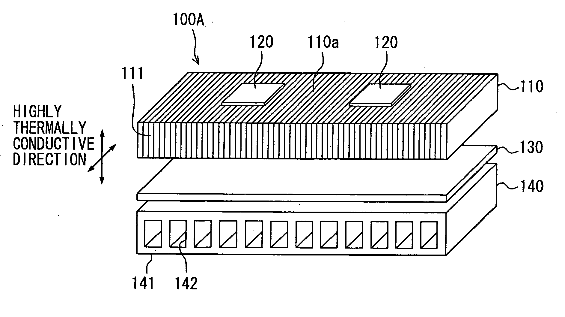
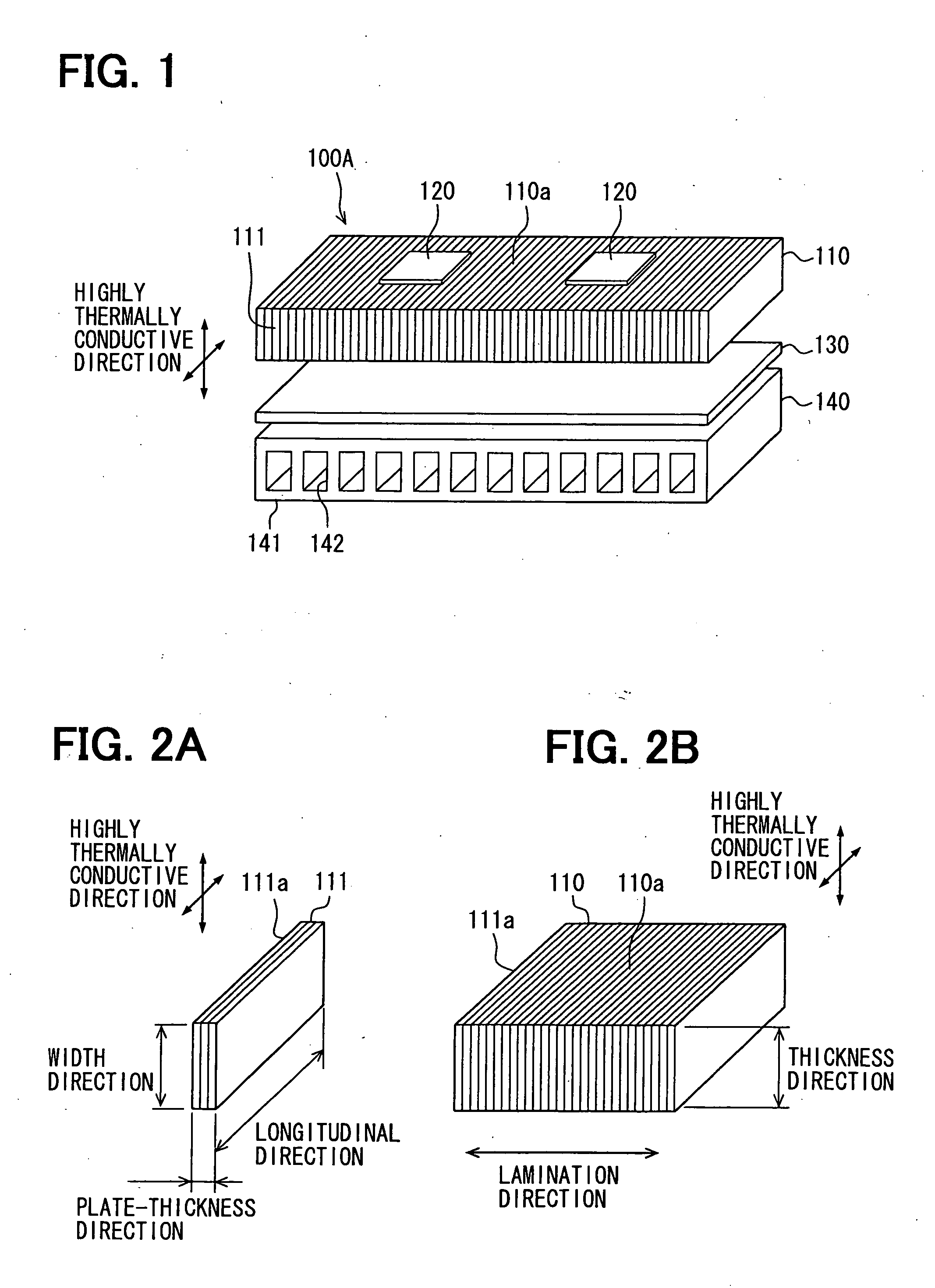
[0028]A cooling apparatus 100A for cooling a heat source in the first embodiment will be described blow with reference to FIG. 1 and FIGS. 2A and 2B. FIG. 1 is an exploded perspective view illustrating the cooling apparatus 100A of the heat source, and FIGS. 2A and 2B are perspective views each illustrating a thermal diffuser 110 made of thermal conductivity plates in FIG. 1.
[0029]As shown in FIG. 1, the cooling apparatus 100A for cooling the heat source (hereinafter, simply referred to as the cooling apparatus 100A) includes the thermal diffuser 110, a heat source 120, an insulating plate 130, and a cooling unit 140. The cooling apparatus 100A cools the heat source 120 by transmitting heat of the heat source 120 to the cooling unit 140 through the thermal diffuser 110.
[0030]As shown in FIG. 2, the thermal diffuser 110 is a plate that efficiently transmits heat of the heat source 120 toward the cooling unit 140, and the thermal diffuser 110 includes multiple thermally-conductive plates 111. Each of the thermally-conductive plates 111 is a very thin plate member having a strip-like shape. The thermally-conductive plate 111 has thermal conductivities in a longitudinal direction and in a width direction better than a thermal conductivity in a plate-thickness direction. The thermally-conductive plate 111 is made of, for example, a graphite material, or alternatively of a composite material, which has graphite and metal. The metal of the above composite material employs, for example, copper and aluminum. Specifically, as above, the graphite material has great thermal conductivities in a plate-thickness direction and in a width direction of the thermally-conductive plate 111. In other words, the graphite material is a highly oriented graphite material having great thermal conductivities in two directions that extend along a plate surface (or a top surface) of the graphite material.
[0031]The thermally-conductive plates 111 are laminated onto one another in the plate-thickness direction to form a plate-shaped laminated body. In the first embodiment, the laminated body serves as the thermal diffuser 110. In other words, in the laminated body, the thermally-conductive plate 111 has a long side 111a that extends in a longitudinal direction, and the long sides 111a forms a plate surface 110a having a plate shape that extends in a lamination direction, in which the thermally-conductive plates 111 are laminated (see FIG. 2B). Furthermore, a direction orthogonal to the plate surface 110a corresponds to a thickness direction of the laminated body having the plate shape. The thermal diffuser 110 has a plate shape that has a dimension in the lamination direction greater than a dimension of the thermally-conductive plate 111 in the width direction. The plate surface 110a is, in other words, a plane defined by (a) the long side 111a and (b) a side that extends in the lamination direction. The thermal diffuser 110 has a dimension in the thickness direction, which dimension is equivalent to a dimension of the thermally-conductive plate 111 in the width direction. As a result, the thermal diffuser 110 has better thermal conductivities in two directions (see FIGS. 2A and 2B in this regard). More specifically, the two directions include the direction of the long side 111a of the plate surface 110a, and the thickness direction of the plate-shaped laminated body.
[0032]It is noted that the thermal diffuser 110 is formed as the laminated body by laminating the multiple thermally-conductive plates 111 onto one another, and then by baking the thermally-conductive plates 111. Alternatively, a gaseous material, such as a highly oriented graphite material, or a composite material having a highly oriented graphite and metal, is sequentially sprayed on a plane to form the laminated body.
[0033]The heat source 120 is a semiconductor device, for example, an IGBT (insulated gate bipolar transistor) or an FWD (flywheel diode), which generates heat when operated. For example, the thermal diffuser 110 includes two plate surfaces 110a (top and bottom plate surfaces 110a). There are multiple heat sources 120 (two generators 120 in the present embodiment), and the heat sources 120 are provided to contact one of the plate surfaces 110a of the thermal diffuser 110.
[0034]The insulating plate 130 is a plate member made of a ceramics for electrically insulating the heat source 120, for example. The insulating plate 130 is provided to contact the other one of the plate surfaces 110a of the thermal diffuser 110 opposite from the one plate surface 110a, to which the heat source 120 is provided.
[0035]The cooling unit 140 is a heat exchanger that cools the heat source 120 by transferring heat of the heat source 120 to a cooling medium that flows through the internal passages 142. The cooling unit 140 is provided to contact a surface of the thermal diffuser 110 opposite from the insulating plate 130. The cooling unit 140 includes a main body part 141 having a plate shape and defining therein the main passages 142. The passages 142 are formed to admit cooling medium (for example, cooling air, coolant) to flow therethrough.
[0036]In the above cooling apparatus 100A, heat of the heat source 120 spreads along the plate surface 110a of the thermal diffuser 110 (or spreads in the direction of the long side 111a) to an outer periphery, and also is transferred in the thickness direction of the thermal diffuser 110. Furthermore, the heat is transferred in a plate-thickness direction of the insulating plate 130 to reach the main body part 141 of the cooling unit 140. In the cooling unit 140, the above transferred heat of the heat source 120 is given to the cooling medium flowing through the internal passages 142, and thereby the heat source 120 is successfully cooled.
[0037]In the present embodiment, the thermally-conductive plate 111 of the thermal diffuser 110 has better thermal conductivities in the longitudinal direction and in the width direction than a thermal conductivity in the plate-thickness direction. The thermal diffuser 110 is made by laminating the thermally-conductive plates 111 in the plate-thickness direction. In the above, the plate surface 110a is formed by the longitudinal sides 111a of the thermally-conductive plates 111 and extends in the lamination direction. Because of the above formed plate surface 110a, it is possible to provide a better thermal conductivity in the longitudinal direction of the thermally-conductive plate 111. Also, in the above configuration, the thickness direction, which is orthogonal to the plate surface 110a of the thermal diffuser 110, coincides with the width direction of the thermally-conductive plate 111 as shown in FIG. 2B. As a result, it is possible to provide a better thermal conductivity in the thickness direction of the thermal diffuser 110. Thereby, the thermal diffuser 110 has better thermal conductivities in two directions (see the highly thermal conductive directions shown in FIGS. 1, 2A and 2B). More specifically; one of the two directions, in which the thermal conductivities act better, is a direction parallel to the plate surface 110a of the thermal diffuser 110 and perpendicular to the lamination direction. The other of the two directions is the thickness direction (or a layer direction) of the thermal diffuser 110. As a result, it is possible to efficiently transfer the heat of the heat source 120 to the cooling unit 140.
Example
Second Embodiment
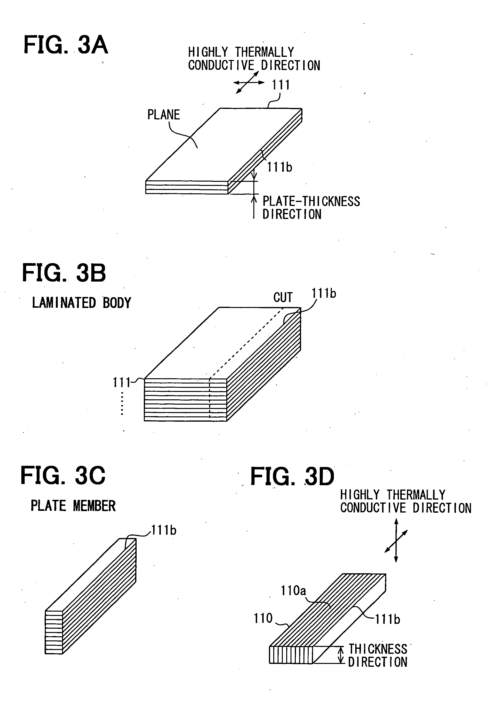
[0038]FIGS. 3A to 3D show a thermal diffuser 110 of the second embodiment, and more specifically show a manufacturing process of the thermal diffuser 110. The method of manufacturing the thermal diffuser 110 in the second embodiment is different from the manufacturing method in the first embodiment (FIG. 1, FIG. 2).
[0039]The method for manufacturing the thermal diffuser 110 will be described below. Firstly, the plate-shaped thermally-conductive plates 111 having a better thermal conductivity in the plane direction than the thermal conductivity in the plate-thickness direction are prepared (FIG. 3A). The thermally-conductive plates 111 are laminated on one another in the plate-thickness direction to form a laminated body (FIG. 3B).
[0040]Next, the laminated body formed as above is cut in the lamination direction along the one side 111b of the thermally-conductive plate 111 to form a plate member as shown in FIG. 3C. Then, in the plate member, the plate surface 110a of the thermal diffuser 110 is defined by a surface made by the lamination of the one sides 111b of the thermally-conductive plates 111 in the lamination direction. Also, the thickness direction of the thermal diffuser 110 is defined to be orthogonal to the plate surface 110a (FIG. 3D).
[0041]As a result, the thermal diffuser 110, which is equivalent to the thermal diffuser 110 described in the first embodiment, is easily formed.
Example
Third Embodiment
[0042]FIGS. 4 to 6 show a cooling apparatus 100B of the third embodiment. In contrast to the first embodiment (FIGS. 1 and 2), the thermal diffuser 110 of the third embodiment is made of multiple thermal diffusers 110A, 110B.
[0043]As shown in FIGS. 4, 5A, and 5B, the thermal diffuser 110 is made of two thermal diffusers (or two laminated bodies). More specifically, the thermal diffuser 110 includes a first thermal diffuser 110A and a second thermal diffuser 1108. Each of the thermal diffusers 110A, 110B is similar to the thermal diffuser 110 described in the first embodiment. The thermal diffuser 110A is arranged such that the lamination direction of the thermally-conductive plates 111 of the thermal diffuser 110A is different from the lamination direction of the thermally-conductive plates 111 of the thermal diffuser 110B. Thus, the adjacent thermal diffusers (laminated bodies) 110A, 110B have the respective lamination directions of the thermally-conductive plates 111 different from each other.
[0044]In other words, in the first thermal diffuser 110A, the lamination direction, in which the thermally-conductive plates 111 are laminated, corresponds to a depth direction in FIG. 5A. Thereby, the first thermal diffuser 110A has better thermal conductivities in a left-right direction of the plate surface 110a in FIG. 5A (or the longitudinal direction of the thermally-conductive plate 111) and in the thickness direction of the first thermal diffuser 110A.
[0045]In contrast, in the second thermal diffuser 110B, a lamination direction, in which the thermally-conductive plates 111 are laminated, corresponds to the left-right direction in FIG. 5A. As a result, the second thermal diffuser 110B has better thermal conductivities in the depth direction of the plate surface 110a in FIG. 5A (or in the longitudinal direction of the thermally-conductive plate 111) and in the thickness direction of the second thermal diffuser 110B.
[0046]The first thermal diffuser 110A and the second thermal diffuser 110B are laminated in the thickness direction, and an inorganic bonding layer (inorganic layer) 112 interposed between the thermal diffusers 110A, 110B bonds the thermal diffusers 110A, 110B each other. The bonding layer 112 includes at least one of titanium (Ti), nickel (Ni), tin (Sn), lead (Pb), and gold (Au). In the present embodiment, the bonding layer 112 is solder having tin (Sn). Solder has a thermal conductivity of 60 W/mK.
[0047]The thermal diffuser 110 formed as above includes the first thermal diffuser 110A and the second thermal diffuser 110B, and the lamination direction of the thermally-conductive plates 111 of the first thermal diffuser 110A is different from the lamination direction of the thermally-conductive plates 111 of the second thermal diffuser 110B. More specifically, the above lamination directions intersect with each other. Specifically, the lamination directions intersect at a right angle (or at the angle of 90 degrees). The angle defined by the lamination directions may be in a range from 85 to 90 degrees in order to enhance the thermal conductivities in the two axial directions along the plate surface 110a.
[0048]In the thermal diffuser 110 of the present embodiment, the plate surface 110a of the first thermal diffuser 110A has a first direction, in which the thermal conductivity of the first thermal diffuser 110A acts better, and the plate surface 110a of the second thermal diffuser 1108 has a second direction, in which the thermal conductivity of the second thermal diffuser 110B acts better. In the thermal diffuser 110 of the present embodiment, the first direction and the second direction define therebetween the angle in a range from 85 to 90 degrees. As a result, when observed as the entirety of the thermal diffuser 110, which has the thermal diffusers 110A, 110B laminated in thickness direction, it is possible to cause the thermal diffuser 110 to have better thermal conductivities in the thickness direction and also in the two directions, which are orthogonal to each other, along the plate surface 110a. Thus, it is possible to provide the thermal diffuser 110 that has thermal conductivities that acts better in three axial directions, and thereby it is possible to efficiently cool the heat source 120.
[0049]FIG. 6 is a chart illustrating a thermal conductivity in the thickness direction of the thermal diffuser 110 made of the multiple thermal diffusers 110A, 1108 as a function of the thermal conductivity of the bonding layer 112. In one model of the present embodiment, each of the thermal diffusers 110A, 1108 has a length of 32 mm, a width of 18 mm, and a thickness of 1 mm. The bonding layer 112 has a thickness of 0.1 mm. In the above dimension, the thermal conductivity in the thickness direction of the thermal diffuser 110 is studied. When the bonding layer 112 (or solder) has the thermal conductivity of 60 W/mK, the thermal conductivity in the thickness direction of the thermal diffuser 110 indicates 600 W/mK. The above value is much higher than the thermal conductivity of copper or aluminum.
[0050]In the embodiment, the thermal diffuser 110 includes two thermal diffusers 110A, 110B. However, the thermal diffuser 110 may alternatively include three or more thermal diffusers that are laminated. In the above alternative case, the adjacent thermal diffusers among the three or more thermal diffusers may be arranged such that the direction, in which one thermal diffuser has a better thermal conductivity, is set different from the direction, in which the adjacent thermal diffuser has a better thermal conductivity. More specifically, the above directions of the adjacent thermal diffusers may define the angle in a range from 85 to 90 degrees.
PUM
Property | Measurement | Unit |
Angle | 85.0 ~ 90.0 | ° |
Thickness | ||
Electrical conductor |
Description & Claims & Application Information
We can also present the details of the Description, Claims and Application information to help users get a comprehensive understanding of the technical details of the patent, such as background art, summary of invention, brief description of drawings, description of embodiments, and other original content. On the other hand, users can also determine the specific scope of protection of the technology through the list of claims; as well as understand the changes in the life cycle of the technology with the presentation of the patent timeline. Login to view more.