Cooking device

a technology of cooking device and cooking chamber, which is applied in the direction of electric/magnetic/electromagnetic heating, stoves or ranges, domestic stoves, etc., can solve the problems of no wiring, noise resistance and productivity improvement, and achieve the effect of eliminating wiring, improving noise resistance and productivity

Active Publication Date: 2011-12-15
PANASONIC INTELLECTUAL PROPERTY MANAGEMENT CO LTD
View PDF8 Cites 23 Cited by
  • Summary
  • Abstract
  • Description
  • Claims
  • Application Information

AI Technical Summary

Benefits of technology

[0008]This configuration enables two-way wireless communication between the operation unit and the device body, and eliminates wiring. No wiring improves noise resistance and productivity.

Problems solved by technology

No wiring improves noise resistance and productivity.

Method used


Image

  • Cooking device
  • Cooking device
  • Cooking device

Examples


first exemplary embodiment

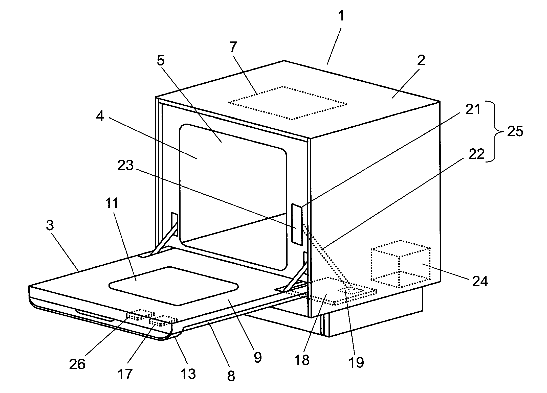
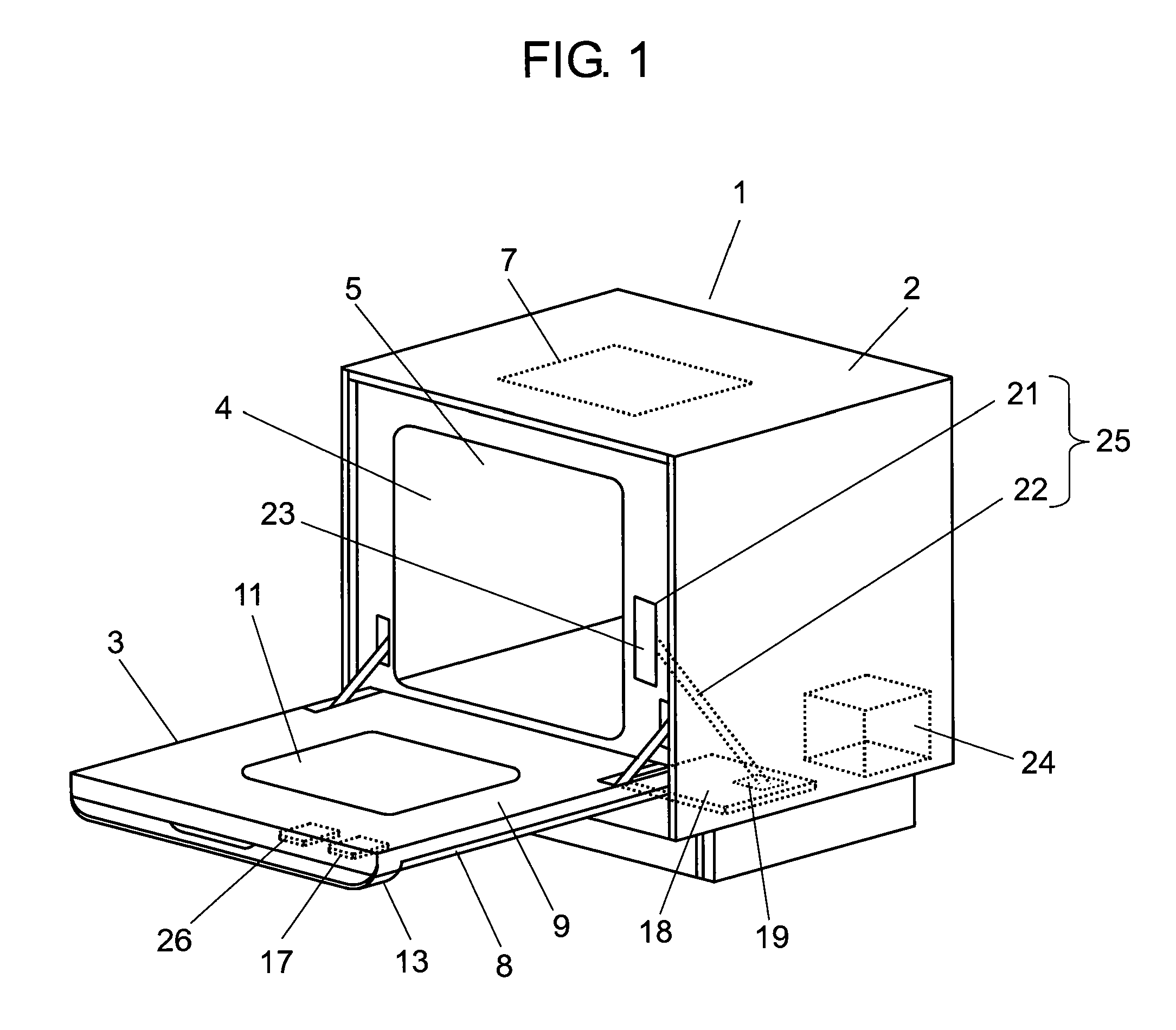
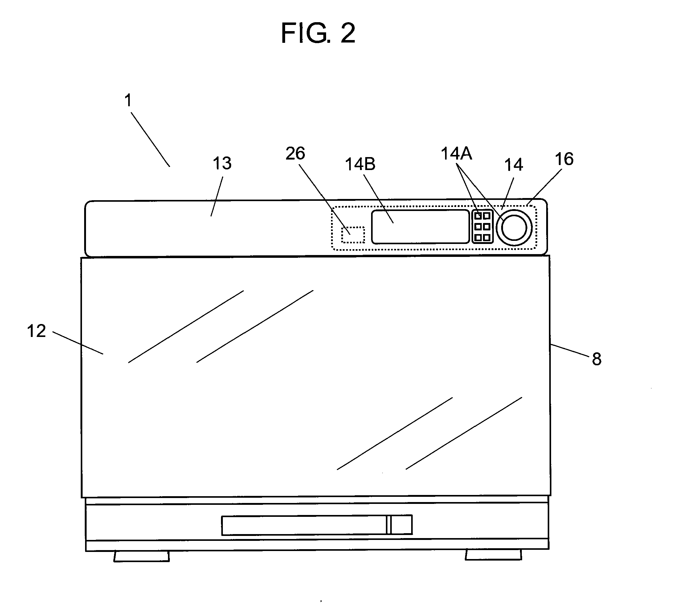
[0015]FIG. 1 is a perspective view of a cooking device in the first exemplary embodiment of the present invention. FIG. 2 is a front view of the cooking device in this exemplary embodiment.

[0016]As shown in FIG. 1, cooking device 1 includes device body 2 whose exterior is covered with a metal plate, and door 3. Heating chamber 4 with opening 5 at the front is provided inside device body 2. Opening 5 of heating chamber 4 is opened and closed by door 3. Door 3 is axially supported at its bottom end, and opens and closes in the vertical direction. Door 3 also covers the entire front face of device body 2.

[0017]Magnetron 24 that generates microwaves of 2450 MHz, which are high-frequency waves, is provided as a heating unit at a lower part of heating chamber 4. Heater 7 is provided on a ceiling of heating unit 4 as another heating unit. An object to be heated inside heating chamber 4 is heated by high-frequency waves of magnetron 24 and radiation heat of heater 7. The object to be heated...


PUM


Abstract

Device body (2) with heating chamber (4), and door (3) that opens and closes opening (5) of heating chamber (4). A door wireless communication unit (17) transmits a control signal from an operation unit provided on door 3 in the form of a wireless signal to main wireless communication unit (19). This configuration eliminates the need of wiring between the operation unit and device body (2). No wiring improves noise resistance and productivity.

Description

TECHNICAL FIELD[0001]The present invention relates to cooking devices in which an operation unit is provided on a door.BACKGROUND ART[0002]A cooking device such as a microwave oven and cooking range has an operation unit where cooking switches are provided. A floor-standing cooking device disclosed in PTL 1 has an operation unit on a door for opening and closing a heating chamber.[0003]FIG. 4 is a perspective view of the cooking device of PTL 1. Cooking device 100 includes device body 102 with heating chamber 101, and door 103 that opens and closes an opening of heating chamber 101. Handle 104 is provided at an upper part of door 103 in the state door 103 is closed. Handle 104 has operation unit 105. FIG. 5 is a sectional view of handle 104. Cooking switch 106 is provided on operation unit 105.[0004]This conventional cooking device 100 does not have operation unit 105 on device body 102. This allows an increase of the capacity of heating chamber 101. In addition, this conventional c...

Claims


Application Information

Patent Timeline
Patent Type & Authority Applications(United States)
IPC IPC(8): H05B6/12
CPCF24C15/02F24C7/082
Inventor SANO, MASAAKIARIMA, SATOSHI
Owner PANASONIC INTELLECTUAL PROPERTY MANAGEMENT CO LTD
Why Eureka
Try Eureka