Wireless blasting vibration monitoring system capable of freely networking and control method

A blasting vibration and monitoring system technology, applied to vibration measurement in solids, measuring vibration, wireless communication, etc., can solve problems such as high cost, poor safety, and poor signal, and achieve low price, low power consumption, and low cost Effect

Inactive Publication Date: 2012-10-17
WUHAN RSM INTELLIGENC GEOTECHN
View PDF5 Cites 0 Cited by
  • Summary
  • Abstract
  • Description
  • Claims
  • Application Information

AI Technical Summary

Problems solved by technology

The acquisition sub-node networks of the above-mentioned wired vibration monitoring systems have great limitations: First, the wiring materials and labor costs are high, especially in mountainous areas, fields and other areas with harsh environments. Often, it takes a few seconds to complete a blasting monitoring. It took one day to carry out wiring; secondly, the blasting vibration monitoring work is mobile at any time, resulting in frequent wiring for on-site monitoring and low work efficiency; in addition, at some special monitoring points, such as behind mountains, wiring cannot be carried out at all, resulting in monitoring work incomplete incomplete
This will cause data leakage and affect the monitoring results.
[0007] To sum up, the existing blasting vibration monitoring system generally has problems such as inconvenient wiring, inconvenient movement, high cost, poor safety, troublesome operation, limited transmission distance between nodes, poor signal, and inability to record offline.

Method used


Image

  • Wireless blasting vibration monitoring system capable of freely networking and control method
  • Wireless blasting vibration monitoring system capable of freely networking and control method
  • Wireless blasting vibration monitoring system capable of freely networking and control method

Examples


Embodiment Construction

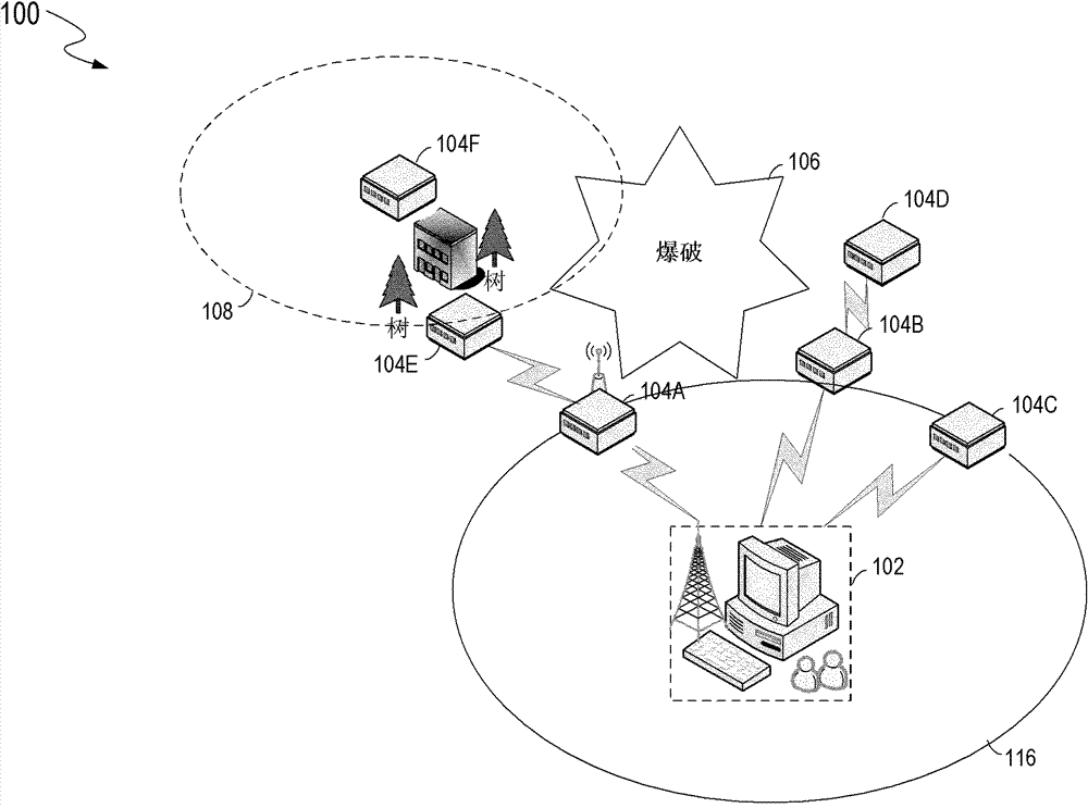
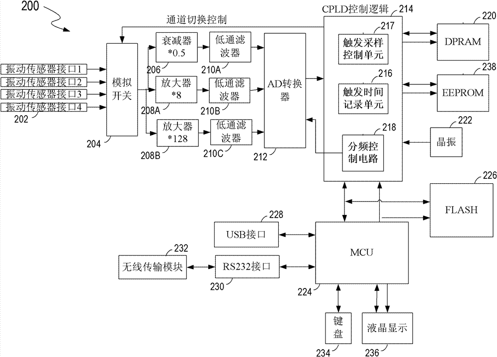
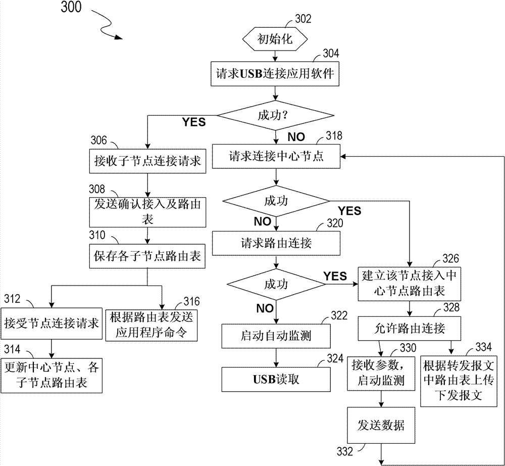
[0038] Below in conjunction with accompanying drawing, the present invention is described in further detail:

[0039] A detailed description will be given below of embodiments of the present invention. While the invention will be described in conjunction with examples, it will be understood that it is not intended to limit the invention to these examples. On the contrary, alternatives, modifications and equivalents are defined within the various scopes of the present invention. The technical solution of the present invention will be described in detail with reference to the drawings and specific embodiments, so as to make the characteristics and advantages of the present invention more obvious.

[0040] Embodiments described herein will be described in conjunction with generally conceptual computer-executable instructions. Computer-executable instructions refer to computer-usable media, such as program modules, that can be executed by one or more computers or other similar...


PUM


Abstract

The invention discloses a wireless blasting vibration monitoring system capable of freely networking and a control method. A vibration sensor interface is respectively connected with a multi-channel analog switch which is connected with an attenuator and an amplifier which are in parallel, the attenuator and the amplifier are respectively connected with a low pass filter, the output end of the low pass filter is connected with the input end of an A / D converter, the output end of the A / D converter is connected with a CPLD (Complex Programable Logic Device) control logic which is respectively connected with a crystal oscillator, a DPRAM (Double Port Random Memory) and an EEPROM (Electrically Erasable Programmable Read - Only Memory), an MCU 224 (Microprogrammed Control Unit) is connected with the CPLD control logic, and a wireless transmission module is connected with the MCU through an RS232 interface. In the control method, an acquiring node is integrally initialized: a USB interface is requested to connect an application software; the acquiring node is successfully connected with a PC machine application software, the acquiring node as an acquiring center works; the acquiring node as an acquiring sub node works under the control of an acquiring center node; and the acquiring node as the acquiring sub node starts automatic monitoring. The invention has the advantages of convenient installation, low cost, high efficiency and stable signal, and solves the problem in the blasting vibration monitoring system.

Description

technical field [0001] The present invention relates to the technical field of geotechnical engineering monitoring instruments, more specifically to a wireless blasting vibration monitoring system that can be freely networked, and also relates to a control method executed by one of the acquisition nodes in the blasting vibration monitoring system, which is used to monitor various Blasting vibration engineering site. Background technique [0002] With the rapid development of my country's economic construction, more and more blasting projects and blasting experiments need to be carried out in cities, mines, roads and bridges, hydroelectric seismic stations and other places with important engineering buildings. Since the shock waves, dust, and noise generated by blasting vibration will cause harm to surrounding buildings, soil topography, and residential areas, the monitoring of blasting vibration in these places is particularly important. [0003] Usually, it is necessary to...

Claims


Application Information

Patent Timeline
Patent Type & Authority Patents(China)
IPC IPC(8): G01H1/00H04W84/18
Inventor 胡纯军毛勇强张杰李长林樊火
Owner WUHAN RSM INTELLIGENC GEOTECHN
Why Eureka
Try Eureka