

Compensation device applied to power amplifier, method for determining pre-distortion of power amplifier, and method for compensating linearity of power amplifier thereof
a technology of compensation device and power amplifier, applied in the direction of transmission monitoring, baseband system details, gain control, etc., can solve the problems of poor communication quality, inability to achieve linearity in power amplifiers, and inducing many harmonics and affecting other channels
- Summary
- Abstract
- Description
- Claims
- Application Information
AI Technical Summary
Benefits of technology
Problems solved by technology
Method used
Image


Examples
first embodiment
[0023]Please refer to FIG. 3. FIG. 3 is a block diagram of a compensation device 300 applied to a power amplifier according to the present invention. Generally speaking, a power amplifier 210 can be applied to an application circuit 200 (such as, a communication system). To facilitate the description, only the power amplifier 210 is shown and other components of the application circuit 200 are omitted in this embodiment. As shown in FIG. 3, the compensation device 300 may include, but is not limited to, a power signal generator 310, a receiving circuit 320, a gain detecting circuit 330, and a pre-distortion determining circuit 340. First, the power signal generator 310 is arranged to provide a first power input signal (such as, SIN1) to the power amplifier 210, such that the power amplifier 210 generates a first power output signal SOUT1 according to the first power input signal SIN1. At this time, the application circuit 200 acquires a first receiving signal SR1 according to the fi...
second embodiment
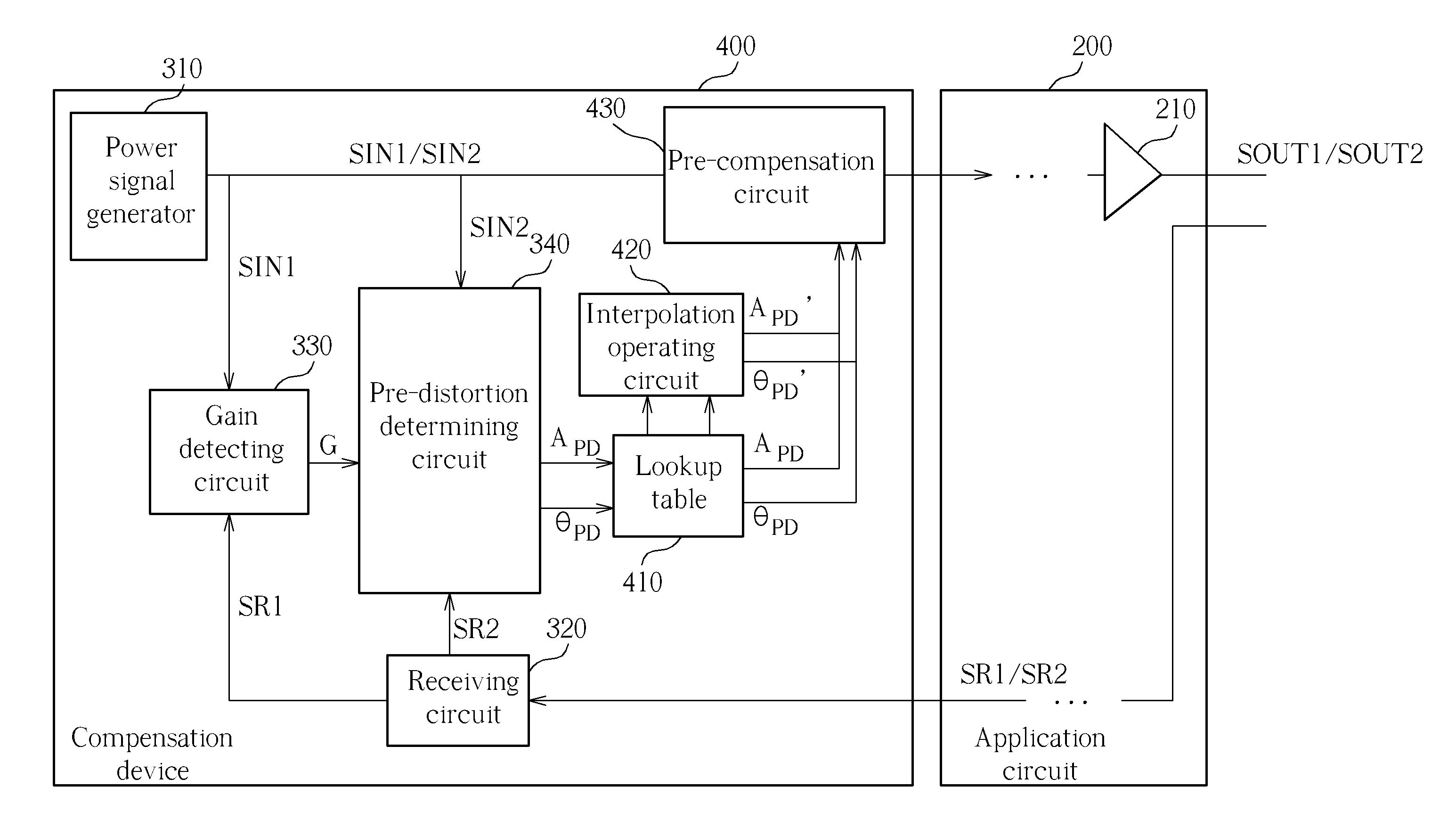
[0025]Please refer to FIG. 4. FIG. 4 is a block diagram of a compensation device 400 applied to a power amplifier according to the present invention. The architecture of the compensation device 400 is similar to that of the compensation device 300 shown in FIG. 3, and the difference between them is that the compensation device 400 further includes a lookup table 410, an interpolation operating circuit 420, and a pre-compensation circuit 430. The lookup table 410 is coupled to the pre-distortion determining circuit 340, and is composed of the plurality of pre-distortion amplitude values APD and the plurality of pre-distortion phase values θPD, which can be presented as the lookup table 50 shown in FIG. 5. Generally speaking, the capacity of the lookup table 410 may be restricted, and thus the interpolation operating circuit 420 can be collocated together in order to save memory space. The interpolation operating circuit 420 is coupled to the lookup table 410, and may be arranged to g...
PUM
 Abstract
Description
Claims
Application Information