Antenna and Sensor System for Sharply Defined Active Sensing Zones

a sensor system and active sensing technology, applied in the field of antenna and sensor system, can solve the problem that conventional systems typically offer little control over the coverage zone, and achieve the effect of enhancing the response slope of the compound antenna structur

Inactive Publication Date: 2011-12-15
PLUS LOCATION SYST USA
View PDF13 Cites 256 Cited by
  • Summary
  • Abstract
  • Description
  • Claims
  • Application Information

AI Technical Summary

Benefits of technology

[0008]In one aspect of the invention, an edge of the shield structure may be aligned between the antenna structure and an edge of the coverage zone for enhancing a response slope of the compound antenna structure.
[0013]The system provides broad uniform coverage in the response zone while providing rapid sharp attenuation at the zone boundaries.

Problems solved by technology

Applicants have found that conventional systems typically offer little control over the coverage zone and may have indistinct regions of fringe operation at the edge of the zone.

Method used


Image

  • Antenna and Sensor System for Sharply Defined Active Sensing Zones
  • Antenna and Sensor System for Sharply Defined Active Sensing Zones
  • Antenna and Sensor System for Sharply Defined Active Sensing Zones

Examples


Embodiment Construction

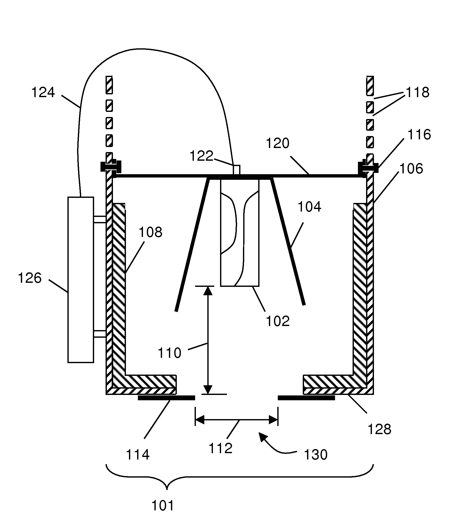
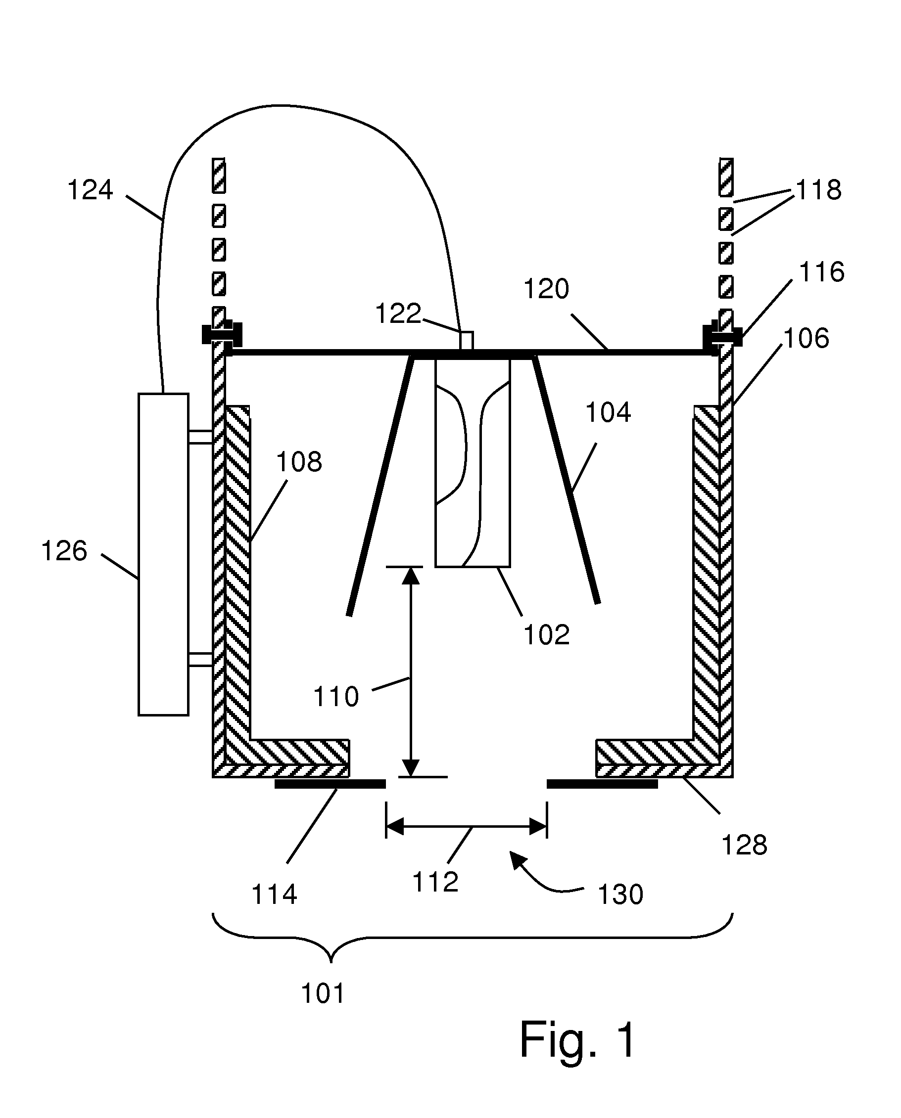
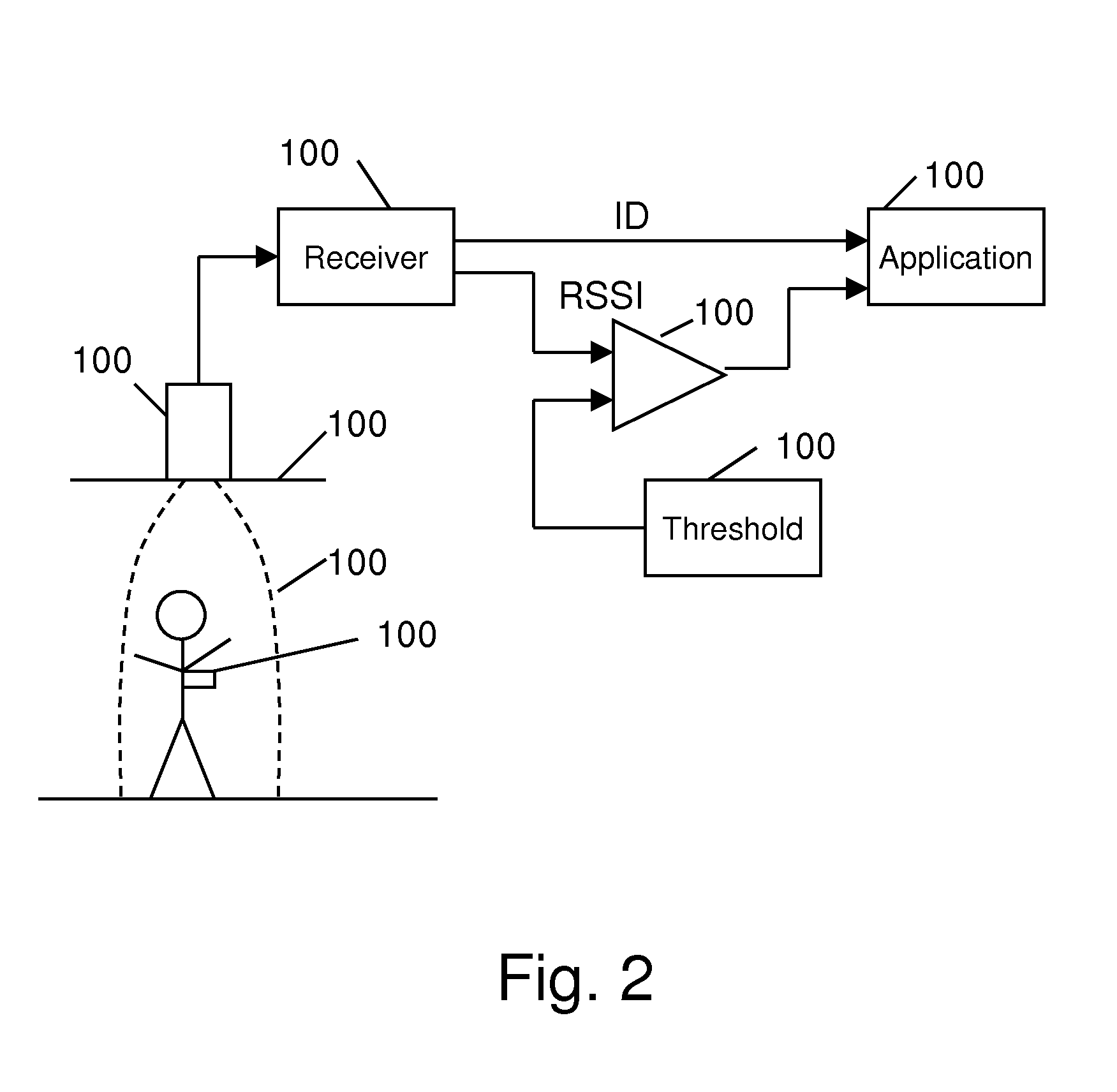
[0028]The current invention relates to a highly directional antenna assembly with frequency characteristics designed for precise detection of signals transmitted by active tags within a defined foot print that corresponds to the antenna's illumination area. The illumination area is precisely defined by the field of view, (FOV), that is, observable by the antenna assembly. Illumination area may also be referred to as the antenna coverage area or sensing zone. The antenna assembly of the current invention allows detection of signals transmitted by tags within precisely defined boundaries or edges of the illumination area. When the tags cross such boundaries, i.e., entering or exiting the illumination area, the presence of a tag within the antenna's illumination area could be detected by a reader within a relatively short boundary resolution. The antenna element 102 connects to a reader 126 via a coaxial cable 124 as shown in FIG. 1. The reader 126 includes receiver circuitry that dete...


PUM

PropertyMeasurementUnit
frequencyaaaaaaaaaa
radio frequencyaaaaaaaaaa
radio frequency attenuationaaaaaaaaaa

Abstract

A sensor system having a sharply defined zone of active sensing comprising a compound antenna system comprising an antenna structure disposed in relation to a shield structure and spaced from the shield structure, the shield structure having an open aperture in front of the antenna structure in the direction of a lobe of sensitivity of the antenna structure. In various embodiments, the shield structure may be layered on the inside between the antenna and the shield structure with an RF absorbing material. The aperture may be formed in part by adjustable panels and the antenna spacing from the aperture may be adjustable by adjusting an antenna mounting position within the shield. The compound antenna system may be coupled to a receiver having a threshold response based on the compound antenna system response characteristic.

Description

RELATED APPLICATIONS[0001]This application claims the benefit under 35 USC 119(e) of U.S. Provisional Application Ser. No. 61 / 353,109 titled “Antenna Assembly that Creates Sharply Defined and Adjustable Zones of Illumination,” filed Jun. 9, 2010 by Beeler et al., which is hereby incorporated herein by reference in its entirety.BACKGROUND[0002]1. Field of the Invention[0003]The present invention pertains generally to the field of antenna and sensor systems, more particularly to systems producing precise zone illumination and responsiveness for use with various systems, for example, RFID tags, location tags, security tags and sensors.[0004]2. Background of the Invention[0005]Within the field of RFID tracking of people and objects, it is often desired to track people or objects within a specific zone. For example, an RFID application may involve detection of people moving through a doorway, or crossing a point in a hallway or aisle without falsely triggering on people just outside the ...

Claims


Application Information

Patent Timeline
Patent Type & Authority Applications(United States)
IPC IPC(8): H01Q1/52H04Q5/22H04W4/00H01Q19/18H01P11/00
CPCH01Q1/2216Y10T29/49016H01Q19/10
Inventor BEELER, BILLVENKATASUBRAMANIAN, ARUN
Owner PLUS LOCATION SYST USA
Why Eureka
Try Eureka