
Connecting tab of battery pack, coupling structure between the connecting tab and wire, and coupling method thereof

Active Publication Date: 2011-12-22
SAMSUNG SDI CO LTD
View PDF39 Cites 18 Cited by
  • Summary
  • Abstract
  • Description
  • Claims
  • Application Information

AI Technical Summary

Benefits of technology

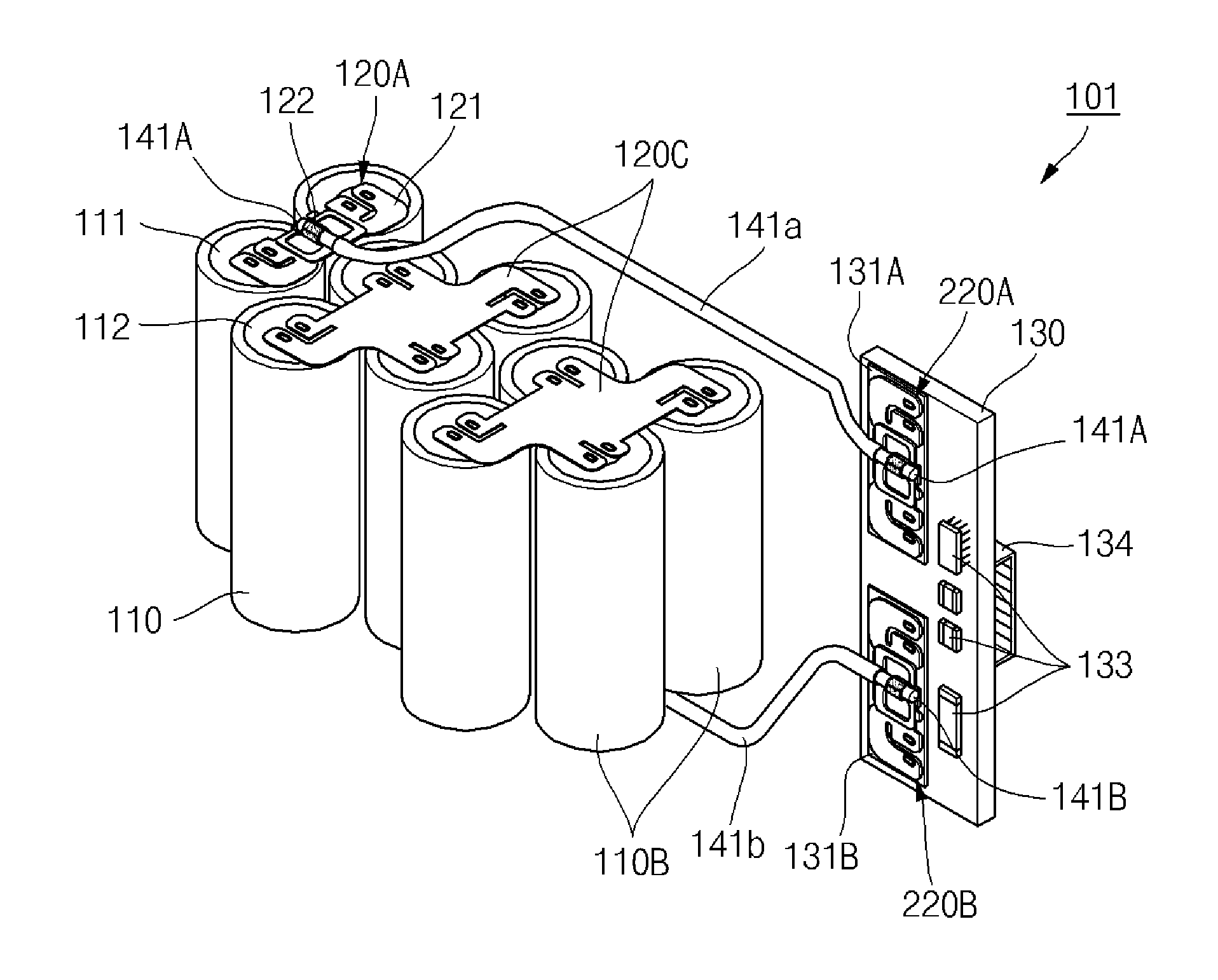
[0008]Embodiments of the present invention also provide a connecting tab of a battery pack, which can quickly and safely couple a wire to be firmly coupled to a battery cell or a protective circuit module, a coupling structure between the connecting tab and a wire, and coupling method thereof.
[0012]In this first embodiment, the second conductive layer may include a pair of coupling protrusions upwardly protruding for connection of the wire. A solder may further be formed on the coupling protrusions and the wire. A hole or a recess may be formed in the second conductive layer for the purpose of preventing the solder from excessively spreading.
[0018]Since the connecting tab of a battery pack according to an embodiment of the present invention includes a more planar first conductive layer, the first conductive layer is more easily welded to the battery cell or the protective circuit module. In addition, since a second conductive layer and a pair of fixing protrusions are formed on the first conductive layer, a wire can be more easily coupled to the second conductive layer and the pair of fixing protrusions.
[0019]In the connection tab of a battery pack according to another embodiment of the present invention, a wire is coupled to a pair of coupling protrusions provided in the connection tab. In another embodiment of the present invention, after coupling the wire to the pair of coupling protrusions, a solder may be formed. In an alternative embodiment of the present invention, after coupling the wire to the pair of coupling protrusions, protrusions are clamped and a solder is formed. Therefore, the coupling structure between the connecting tab and the wire can allow the connecting tab and the wire to be firmly coupled to each other.
[0021]In the coupling method of the wire and the connecting tab of the battery pack according to another embodiment of the present invention, the connecting tab is connected to a battery cell or a protective circuit module and the wire is coupled to a pair of coupling protrusions provided in the connection tab. In an alternative embodiment of the present invention, after coupling the wire to the pair of coupling protrusions, a solder may be formed. In a further embodiment of the present invention, after coupling the wire to the pair of coupling protrusions, the coupling protrusions are clamped. Furthermore, after clamping the coupling protrusions, a solder may be formed. Therefore, the time required for coupling the connecting tab and the wire to each other is shortened. In addition, since there is no dangerous factor for the entire coupling time, improved working safety is ensured.

Problems solved by technology

In general, it is often difficult to use a single battery cell as a power supply for electronic equipment or electrically powered equipment such as a notebook computer, an electrically powered tool, an electric bicycle or an electrically powered scooter.
Further, with the coupling structure, even when the temperature of the coupling structure rises due to a large current flowing through the wire, resulting in melting of the solder, the wire coupled to the pair of coupling protrusions inhibits the wire from being easily separated from the connecting tab.

Method used


Image

  • Connecting tab of battery pack, coupling structure between the connecting tab and wire, and coupling method thereof
  • Connecting tab of battery pack, coupling structure between the connecting tab and wire, and coupling method thereof
  • Connecting tab of battery pack, coupling structure between the connecting tab and wire, and coupling method thereof

Examples


first embodiment

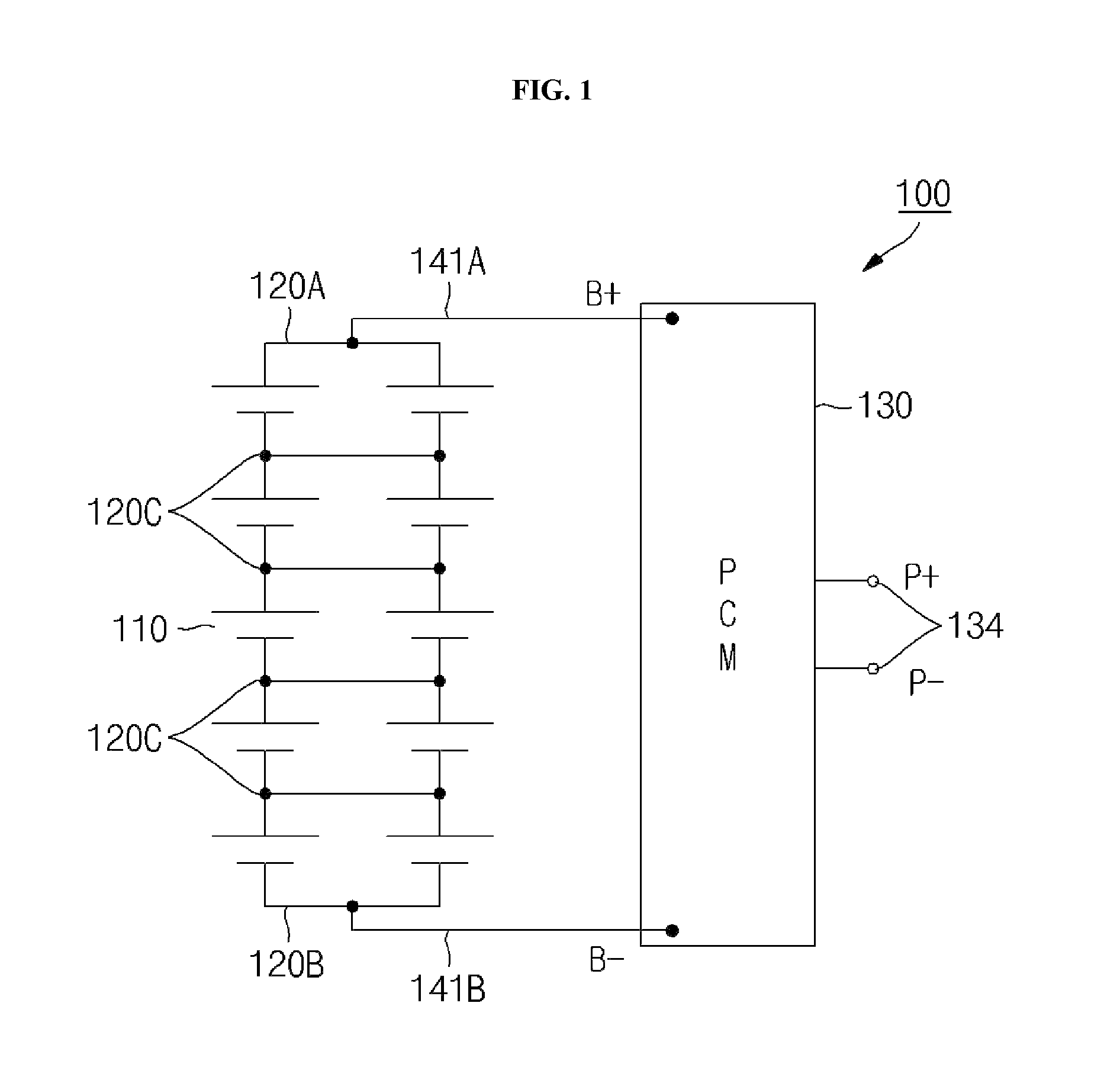
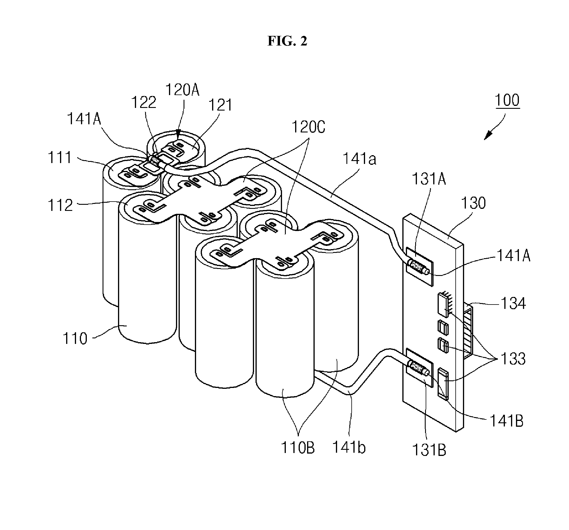
[0009]According to the present invention, a connecting tab coupled to a battery cell or a protective circuit module includes a first conductive layer electrically connected to the battery cell or the protective circuit module, and a second conductive layer formed on the first conductive layer and coupled to a wire.

[0010]In this first embodiment, a connecting region through which the first conductive layer and the second conductive layer are connected to each other may further be formed at each of an end of the first conductive layer and an end of the second conductive layer.

[0011]In this first embodiment, the first conductive layer and the second conductive layer may be made of the same material or different materials each including a clad.

[0012]In this first embodiment, the second conductive layer may include a pair of coupling protrusions upwardly protruding for connection of the wire. A solder may further be formed on the coupling protrusions and the wire. A hole or a recess may ...

second embodiment

[0013]According to the present invention, a coupling method may include preparing a connecting tab including a first conductive layer and a second conductive layer connected to each other through a connecting region, and a pair of coupling protrusions upwardly protruding from the second conductive layer, attaching the connecting tab to a battery cell or a protective circuit module, and coupling a wire to the pair of coupling protrusions of the connecting tab.

[0014]Allowing the second conductive layer and the pair of coupling protrusions to be positioned in the second embodiment on the first conductive layer by bending the connecting region may further be performed between the preparing of the connecting tab and the attaching of the connecting tab.

[0015]The coupling of the wire may be performed in the second embodiment such that the pair of coupling protrusions are clamped after the wire is inserted into the pair of coupling protrusions.

[0016]The coupling of the wire may be performed...


PUM

PropertyMeasurementUnit
Areaaaaaaaaaaa

Abstract

Embodiments of the present invention provide a connecting tab of a battery pack, which allows a wire to be firmly coupled to a battery cell or a protective circuit module, a coupling structure between the connecting tab and a wire, and coupling method thereof. In one embodiment of the present invention, the connecting tab coupled to a battery cell or a protective circuit module includes a first conductive layer electrically connected to the battery cell or the protective circuit module, and a second conductive layer formed on the first conductive layer and coupled to a wire. The second conductive layer may include a pair of coupling protrusions upwardly protruding for connection of the wire. A solder may further be formed on the coupling protrusions and the wire.

Description

RELATED APPLICATIONS[0001]This application claims the benefit of U.S. Provisional Application No. 61 / 356,983, filed Jun. 21, 2010, entitled CONNECTING TAB OF BATTERY PACK, COUPLING STRUCTURE BETWEEN THE CONNECTING TAB AND WIRE AND COUPLING METHOD which is hereby incorporated in its entirety by reference herein.DETAILED DESCRIPTION OF THE INVENTION[0002]1. Technical Field[0003]Embodiments of the present invention relate to a connecting tab of a battery pack, a coupling structure between the connecting tab and a wire, and coupling method thereof.[0004]2. Background Art[0005]In general, it is often difficult to use a single battery cell as a power supply for electronic equipment or electrically powered equipment such as a notebook computer, an electrically powered tool, an electric bicycle or an electrically powered scooter. Therefore, a battery pack used as a power supply for such electronic equipment or electrically powered equipment includes a plurality of battery cells connected in...

Claims


Application Information

Patent Timeline
IPC IPC(8): H01R4/00H01R43/00H01R13/02H01M50/50H01M50/503
CPCH01M2/20Y10T29/49117Y02E60/12H01M2/204Y02E60/10H01M50/50H01M50/503H01M50/531H01M50/543H01M50/572
Inventor PARK, HANKYU
Owner SAMSUNG SDI CO LTD
Learn More