Construction vehicle

a construction vehicle and engine technology, applied in mechanical devices, transportation and packaging, road transportation, etc., can solve the problems of not examining the ideal combination of conditions, operator may experience an odd sensation, etc., and achieve the effect of good fuel economy, higher horsepower, and convenient operation

Active Publication Date: 2011-12-22
KOMATSU LTD
View PDF9 Cites 21 Cited by
  • Summary
  • Abstract
  • Description
  • Claims
  • Application Information

AI Technical Summary

Benefits of technology

[0015]Consequently, the second condition is set more loosely than the first condition, so work can usually be carried out with good fuel economy by controlling the absorption torque of the travel hydraulic pump so that there is matching only on the high-engine speed side when the first condition needs to be met, and so that there is matching on the low-engine speed side when at least one part of the second condition is met, and when more horsepower is needed, there will be matching on the high-engine speed side so that higher horsepower is obtained at the travel hydraulic pump.
[0016]Since condition with an optimal lower limit are set as the second condition for returning from high-engine speed matching to low-engine speed matching, control that is different from what the driver intended, shocks during switching, and the like can be eliminated, and the optimal switching conditions can be set. As a result, the driver will not experience any odd sensation or shocks during control switching, so the work can be carried out more pleasantly.

Problems solved by technology

Nevertheless, the following problems are encountered with the conventional construction vehicles mentioned above.
However, the above publications do not examine the ideal combination of conditions in returning the matching point of the absorption torque curve of the HST pump from the high-engine speed side to the low-engine speed side after switching from the low-engine speed side to the high-engine speed side.
Accordingly, if the contents of the above publications are combined, there is the risk that the operator may experience an odd sensation, such as a jolt during switching, which is control other than what the operator intended.

Method used


Image

  • Construction vehicle
  • Construction vehicle
  • Construction vehicle

Examples


embodiment 1

[0027]A wheel loader (construction vehicle) 50 pertaining to an embodiment of the present invention will now be described through reference to FIGS. 1 to 6.

Overall Configuration of Wheel Loader 50

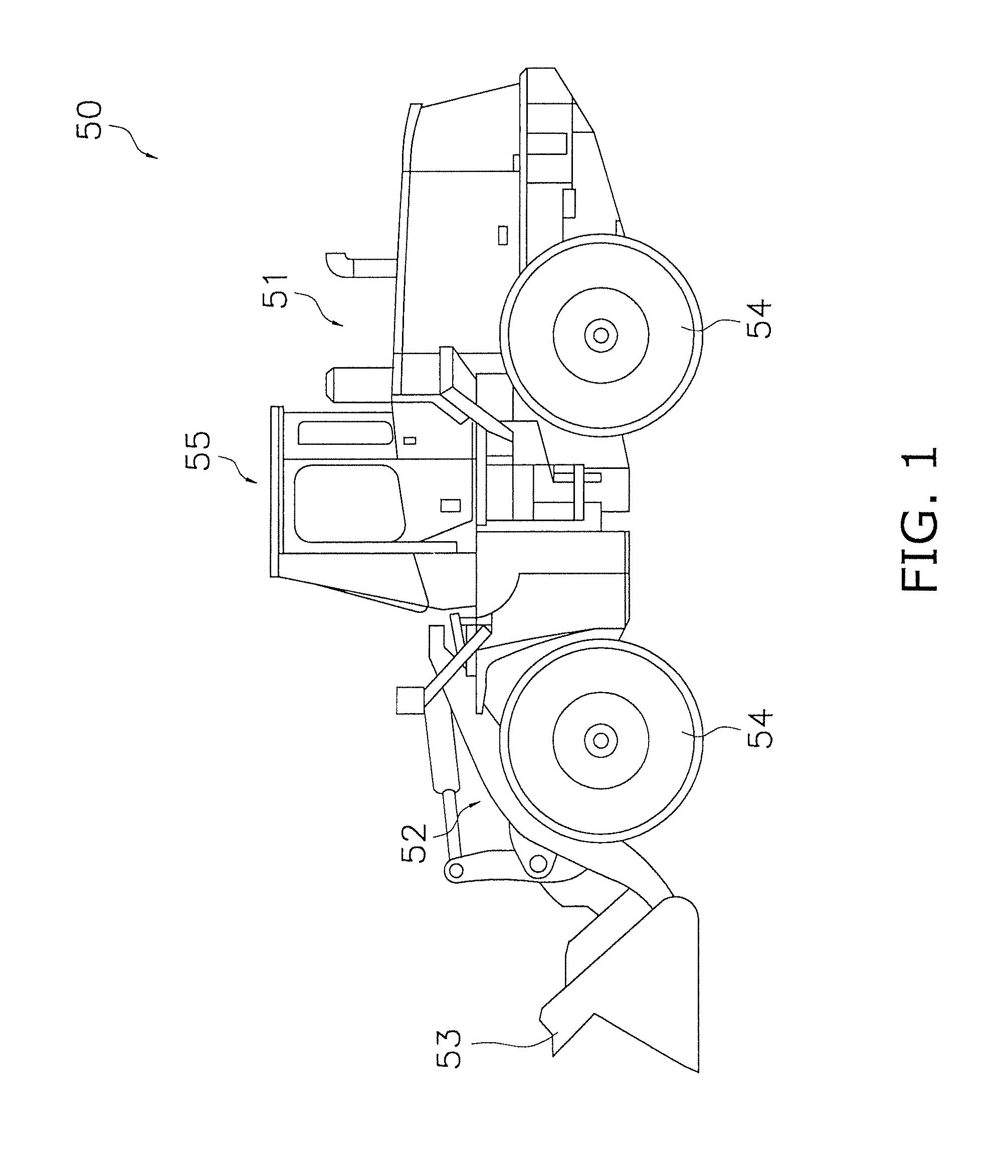
[0028]As shown in FIG. 1, the wheel loader (construction vehicle) 50 pertaining to this embodiment comprises a vehicle body 51, a lift arm (working unit) 52 mounted to the front part of the vehicle body 51, a bucket (working unit) 53 attached to the distal end of this lift arm 52, four tires 54 that rotate while supporting the vehicle body 51 and allow the vehicle body 51 to travel, and a cab 55 installed on top of the vehicle body 51.

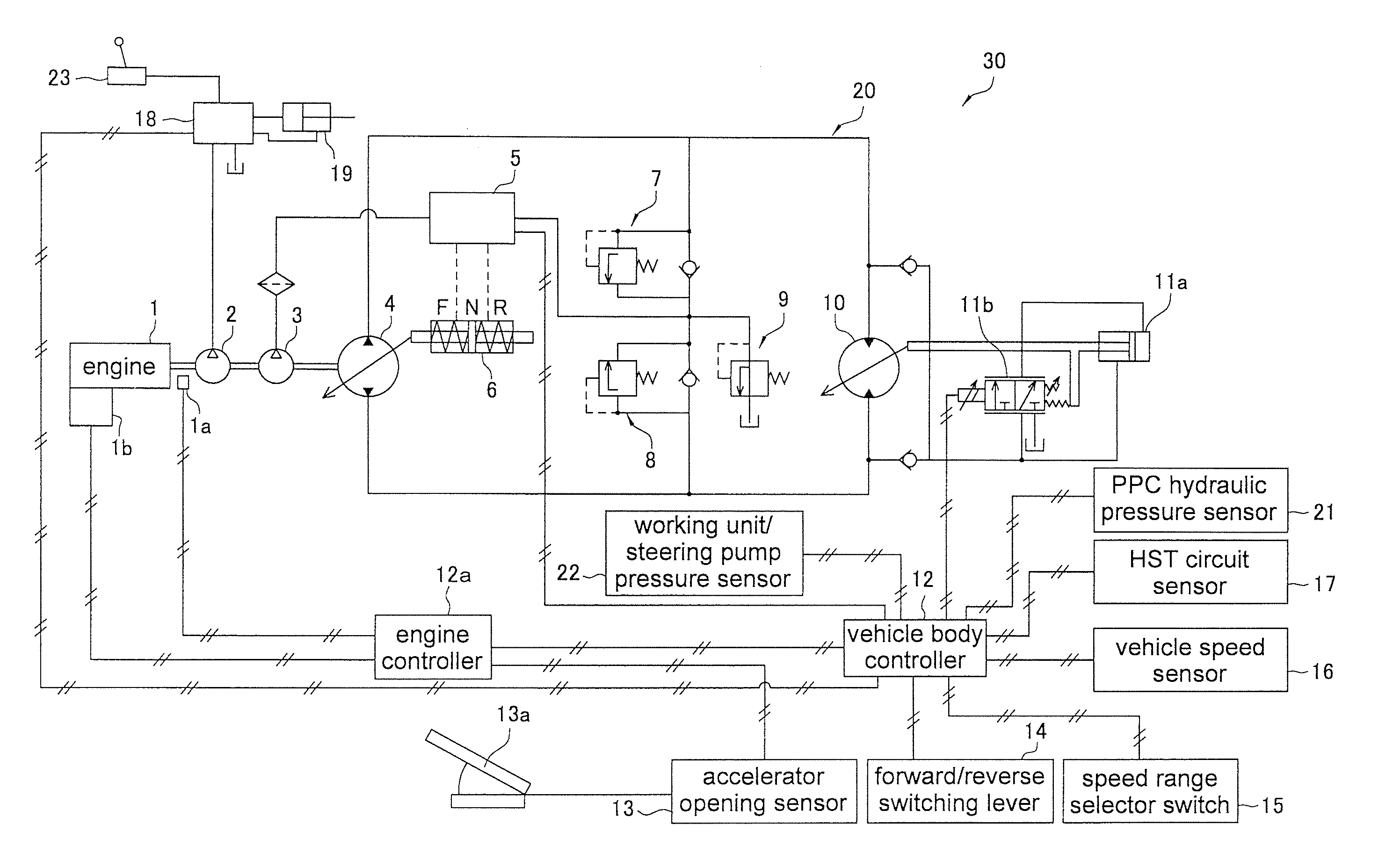
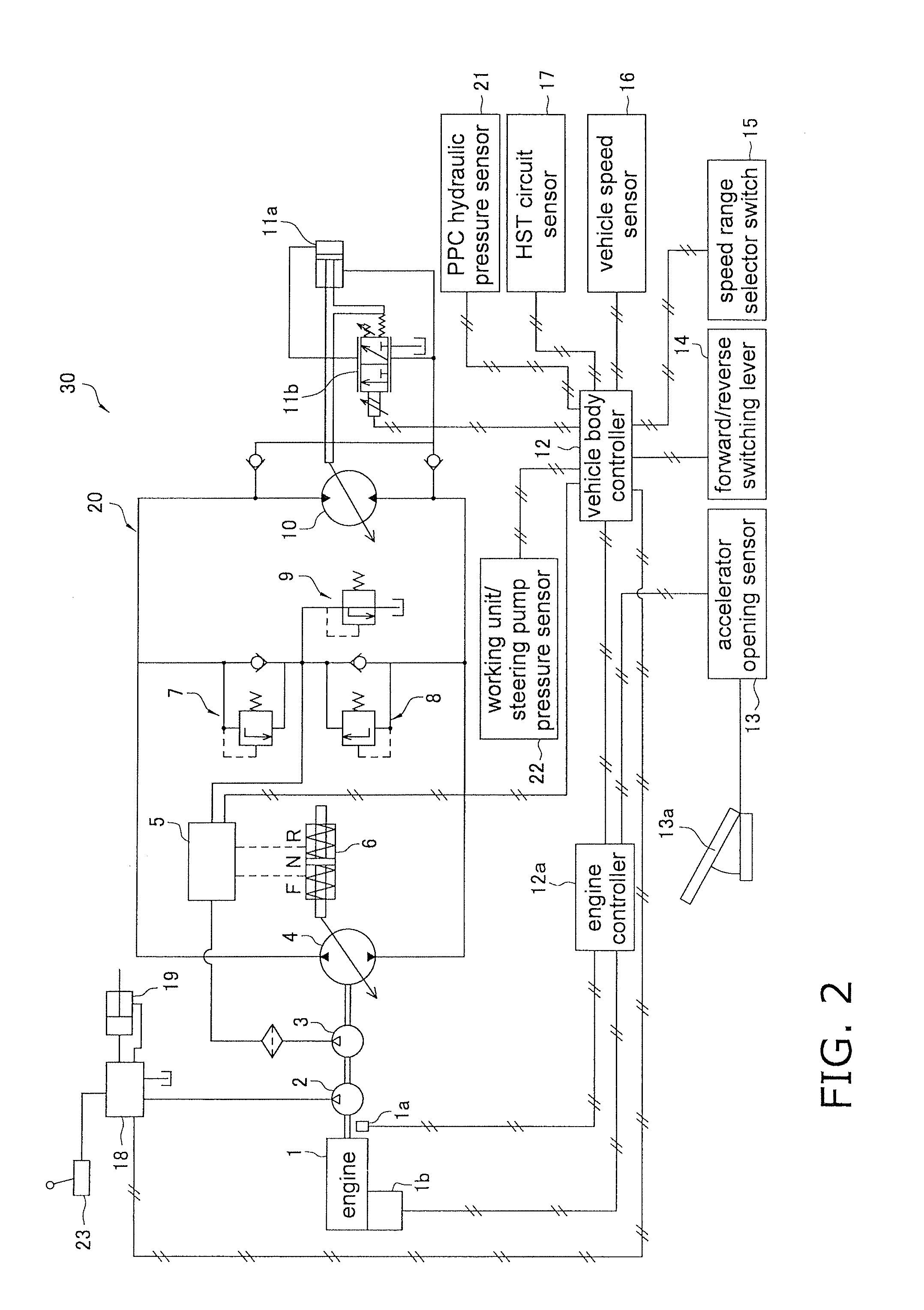
[0029]The vehicle body 51 has an engine compartment that accommodates an engine 1 (see FIG. 2), a control valve 18 for driving the lift arm 52 and the bucket 53 (see FIG. 2), and a vehicle body controller 12 that controls actuators (a working unit hydraulic cylinder 19 and a travel hydraulic motor 10) and so forth. As shown in FIG. 2, the engine 1, the vehicle...

embodiment 2

[0098]Another embodiment of the present invention will be described below.

[0099]In this embodiment, control is performed as follows as another example of control during hill climbing as discussed above.

Control During Hill Climbing-II

[0100]In this embodiment, as another example of control during hill climbing, as shown in the lower half of FIG. 4, the absorption torque curve shown in FIG. 3 is switched from B1 to A1, and the matching point is shifted from MP1 on the low-engine speed side to MP2 on the high-engine speed side when the following conditions are met for vehicle speed, accelerator opening, engine speed, and output torque of the engine controller 12a.

[0101]More specifically, as the first condition, control is performed so that the absorption torque curve of the HST pump 4 is switched from B1, with matching on the low-engine speed side, to A1, with matching on the high-engine speed side, when the following conditions are met:

[0102]a) vehicle speed is at least 10 km / h (clutc...

embodiment 3

[0117]Yet another embodiment of the present invention will now be described.

[0118]In this embodiment, the following control is performed as another example instead of the “Control in Work During Medium- to High-Speed Travel-I” described in Embodiment 1 above.

[0119]Control in Work During Medium- to High-Speed Travel-II

[0120]In this embodiment, as another example of control in work during medium- to high-speed travel, as shown in the lower half of FIG. 5, the absorption torque curve shown in FIG. 3 is switched from B1 to A1, and the matching point is shifted from MP1 on the low-engine speed side to MP2 on the high-engine speed side when the following conditions are met for vehicle speed, accelerator opening, engine speed, and the usage state of the working unit lever 23 or steering lever.

[0121]More specifically, as a fourth condition, control is performed so that the absorption torque curve of the HST pump 4 is switched from B1, with matching on the low-engine speed side, to A1, with ...


PUM


Abstract

A wheel loader (50) is designed so that when a specific first condition is met for vehicle speed, accelerator opening, engine speed, and HST pressure, the engine absorption torque curve of an HST pump (4) is switched to shift the matching point from the low-engine speed side to the high-engine speed side. On the other hand, if a second condition is met for vehicle speed and HST pressure, control is performed so that the absorption torque curve of the HST pump (4) is returned from the high-engine speed side to the low-engine speed side.

Description

CROSS-REFERENCE TO RELATED APPLICATIONS[0001]This national phase application claims priority to Japanese Patent Application No. 2009-074760 filed on Mar. 25, 2009. The entire disclosure of Japanese Patent Application No. 2009-074760 is hereby incorporated herein by reference.TECHNICAL FIELD[0002]The present invention relates to a construction vehicle that travels by driving a travel hydraulic motor with hydraulic fluid discharged from a hydraulic pump driven by an engine.BACKGROUND ART[0003]In general, a wheel loader or other such construction vehicle is equipped with what is called an HST (hydro-static transmission), with which an engine drives a hydraulic pump, and a travel hydraulic motor is driven by the hydraulic fluid discharged from the hydraulic pump.[0004]With an HST type of construction vehicle such as this, the speed and traction of the vehicle can be controlled by controlling the engine speed, the volume of the hydraulic pump, and the volume of the travel hydraulic motor...

Claims


Application Information

Patent Timeline
Patent Type & Authority Applications(United States)
IPC IPC(8): E02F9/22F16H61/431F16H61/468
CPCB60W10/06F16H61/468B60W30/1882B60W2710/0666E02F9/2289E02F9/2235E02F9/2246E02F9/2253E02F9/2292E02F9/2296F16H61/421F16H61/431Y02T10/76F16H2059/6861B60W10/103Y02T10/60
Inventor SHIRAO, ATSUSHIIKARI, MASANORI
Owner KOMATSU LTD
Why Eureka
Try Eureka