Welding wire feeder with magnetic rotational speed sensor

Inactive Publication Date: 2011-12-22
ILLINOIS TOOL WORKS INC
View PDF3 Cites 17 Cited by
  • Summary
  • Abstract
  • Description
  • Claims
  • Application Information

AI Technical Summary

Problems solved by technology

Unfortunately, programmed motor characterization and resistance and voltage slope methods may provide imprecise measurements and data.
However, optical tachometers, which may be mounted to a motor shaft of the wire feeder motor, are prone to failure in high temperature environments.
Additionally, dust or contaminants in a weldin

Method used


Image

  • Welding wire feeder with magnetic rotational speed sensor
  • Welding wire feeder with magnetic rotational speed sensor
  • Welding wire feeder with magnetic rotational speed sensor

Examples


Embodiment Construction

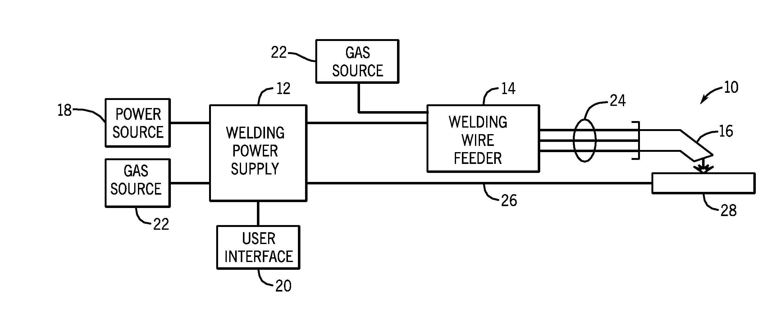
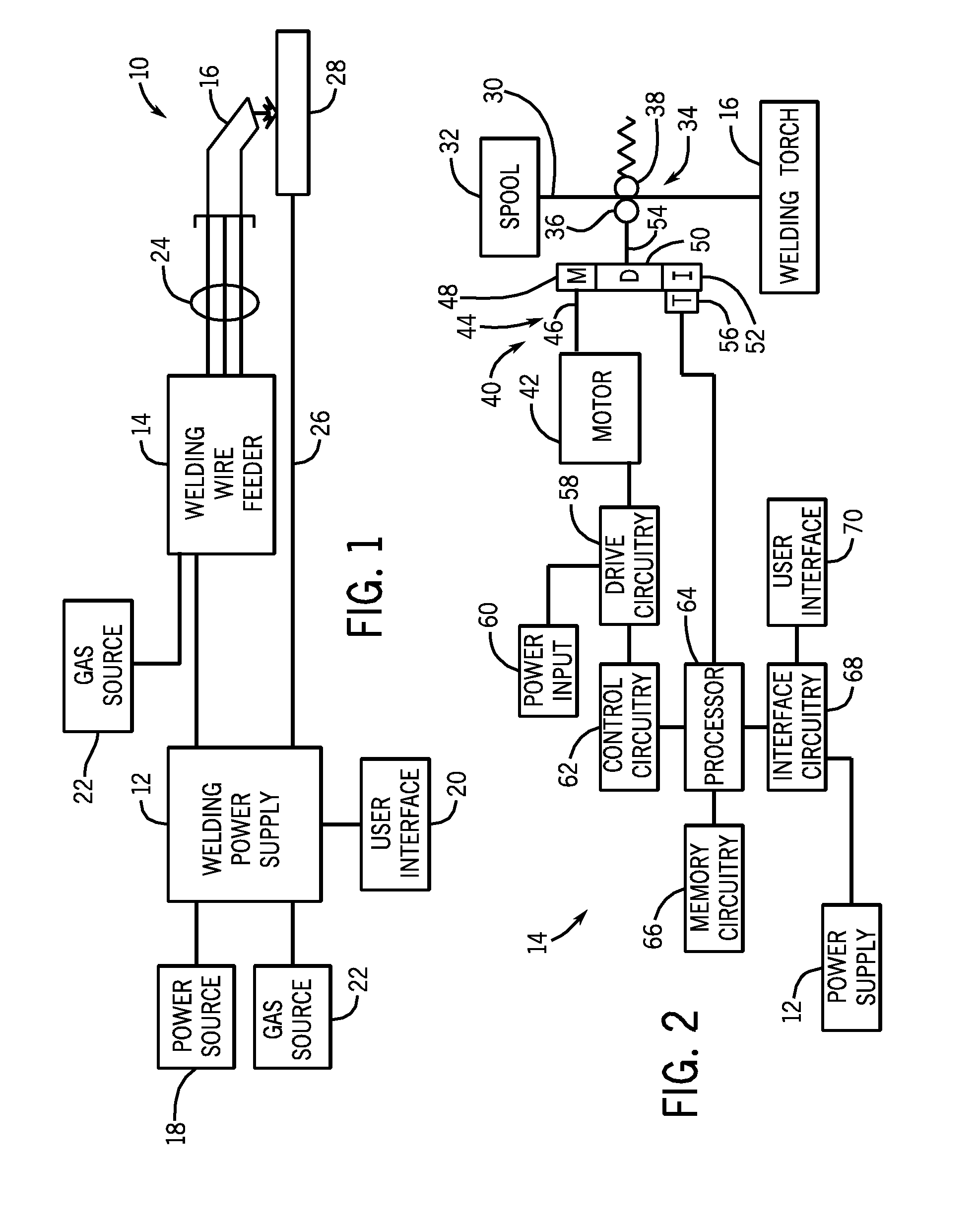
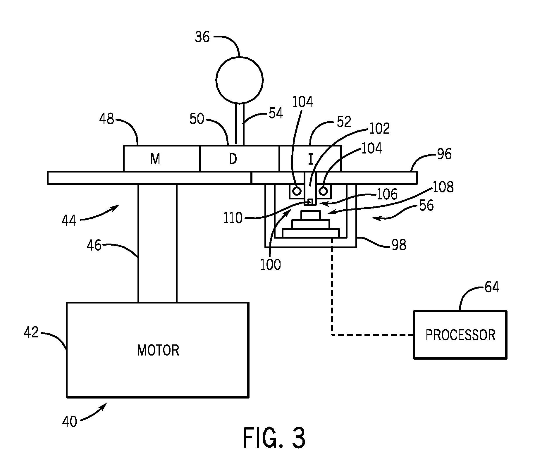
[0014]The present disclosure describes exemplary embodiments of a welding wire feeder having a magnetic wire feed speed sensor. The welding wire feeder includes a motor configured to drive a roll to feed a welding wire to a welding torch. The motor further drives an idler gear, the rotation of which is measured by the magnetic wire feed speed sensor by calculating an angular position and velocity of the idler gear. Rotation of another gear or rotating component of the system could be similarly measured. More specifically, in the embodiment described, the angular position and velocity are measured using a magnet disposed on a shaft coupled the idler gear and positioned over an integrated circuit to sample the angular position of the shaft at a regular interval. The angular position data is then used to determine the angular velocity of the idler gear, which can be further converted into a wire feed speed measurement.

[0015]As will be appreciated, the magnetic wire feed speed sensor ma...


PUM

PropertyMeasurementUnit
Diameteraaaaaaaaaa
Magnetic fieldaaaaaaaaaa
Ratioaaaaaaaaaa

Abstract

A welding wire feeder includes a magnetic rotational sensor system configured to measure a parameter indicative of a wire feed speed of the welding wire feeder. The magnetic rotational sensor system includes a dipole magnet coupled to a gear driven by an electric motor of the welding wire feeder and a magnetic sensor disposed adjacent to the dipole magnet and configured to measure an angular position of the dipole magnet. The magnetic rotational sensor system also includes a processor configured to receive signals of the angular position measured by the magnetic sensor and to calculate a wire feed speed of the welding wire feeder based upon the angular position signals and configuration parameters of the welding wire feeder.

Description

CROSS REFERENCE TO RELATED APPLICATIONS[0001]This application is a Non-Provisional Patent Application of U.S. Provisional Patent Application No. 61 / 355,815 entitled “Magnetic Rotational Speed Sensor in a Welding Wirefeeder”, filed Jun. 17, 2010, which is herein incorporated by reference.BACKGROUND[0002]The invention relates generally to welding systems, and, more particularly, to a welding wire feeder with a magnetic rotational speed sensor.[0003]Welding is a process that has become increasingly ubiquitous in various industries and applications. Such welding operations rely on a variety of types of equipment to ensure the supply of welding consumables (e.g., wire feed, shielding gas, etc.) is provided to the weld in an appropriate amount at the desired time. For example, metal inert gas (MIG) welding typically relies on a wire feeder to ensure the appropriate advance of welding wire to a welding torch, with the wire establishing the welding arc and being consumed as welding progress...

Claims


Application Information

Patent Timeline
IPC IPC(8): B23K9/10
CPCB23K9/1336B23K9/125B23K9/133B23K9/12
Inventor OTT, BRIAN LEEOVERESCH, JEREMY DANIEL
Owner ILLINOIS TOOL WORKS INC
Why Eureka
Try Eureka