Heat sink system

a heat sink and heat sink technology, applied in the direction of fixed installation, lighting and heating apparatus, lighting support devices, etc., can solve the problems of inability to replace a non-functioning fan, and affecting the operation of the devi

Active Publication Date: 2011-12-22
LIGHT EMITTING DESIGN INC
View PDF7 Cites 44 Cited by
  • Summary
  • Abstract
  • Description
  • Claims
  • Application Information

AI Technical Summary

Benefits of technology

The heat sink system further includes a plurality of cooling fins coupled to and extending away from the inner heat sink. An outer heat sink coupled to the cooling fins is offset from the inner heat sink to permit air flow therebetween and over the cooling fins. This allows the heat sink system to cool the inner heat sink, the outer heat sink and the cooling fins via air convection. This effectively draws heat energy away from the lighting assembly to cool the LEDs and the PCB board. In turn, the LEDs last longer and are more luminous.

Problems solved by technology

In small electronic packages or where it is desirable to minimize the amount of energy expended to cool the electronic components, forced convection may be undesirable.
Moreover, reliance on the fans can be detrimental to the operation of the device should the fan become nonoperational.
In some circumstances replacing a nonfunctioning fan could be a maintenance problem.
These assemblies are typically exposed to natural environmental conditions and may be exposed to high ambient operating temperatures—especially during the daytime, in warmer climates and in the summer.
When coupled with the self-generated heat of the LEDs in the assembly, the resulting temperature within the assembly may affect LED performance.
In fact, LED performance tends to substantially degrade at higher operating temperatures because LEDs have a negative temperature coefficient of light emission.
For example, LED light intensity is halved at an ambient temperature of 80° Celsius (“C”) compared to 25° C. This naturally shortens the lifespan of the LED and reduces light output.

Method used


Image

  • Heat sink system
  • Heat sink system
  • Heat sink system

Examples


Embodiment Construction

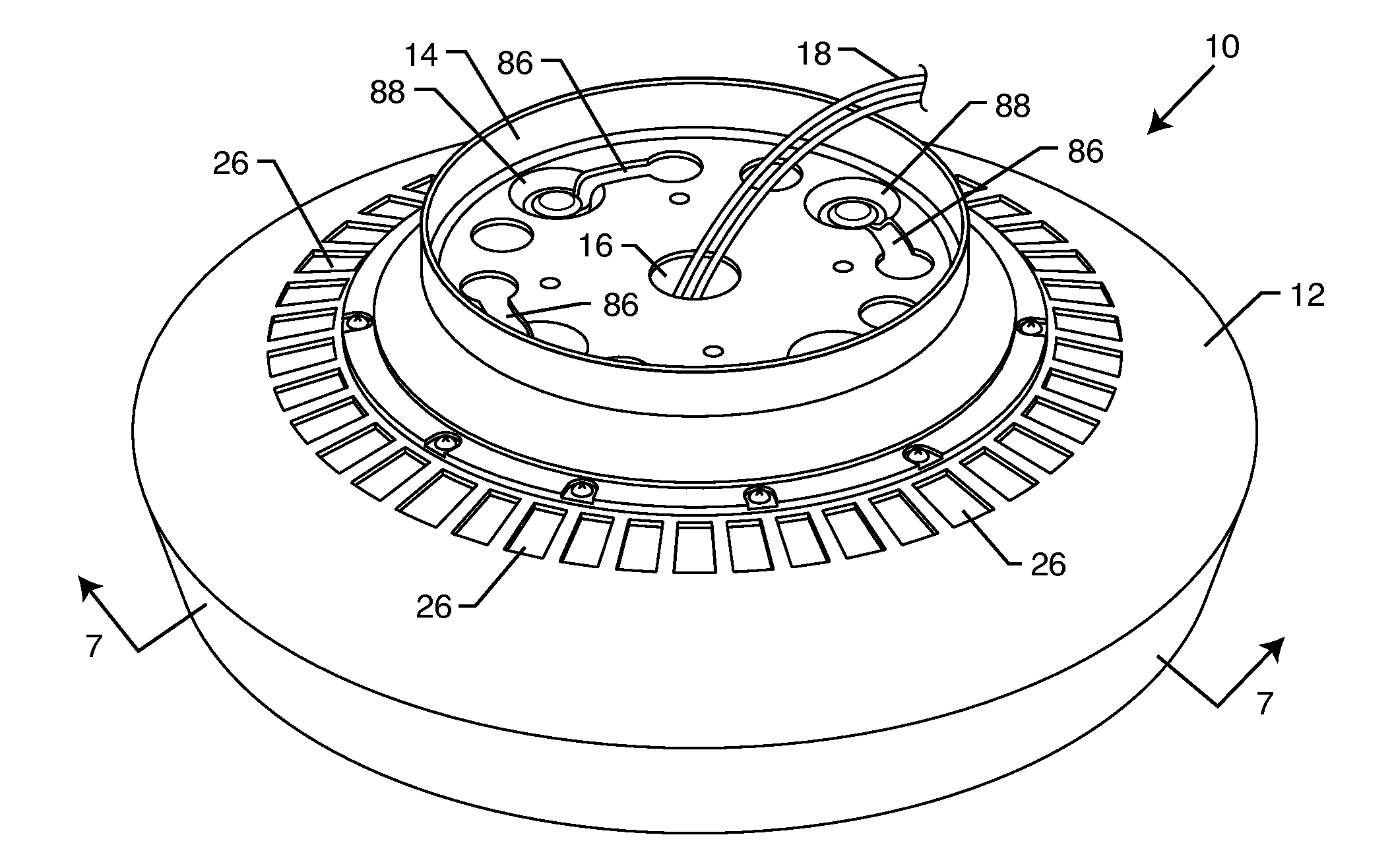
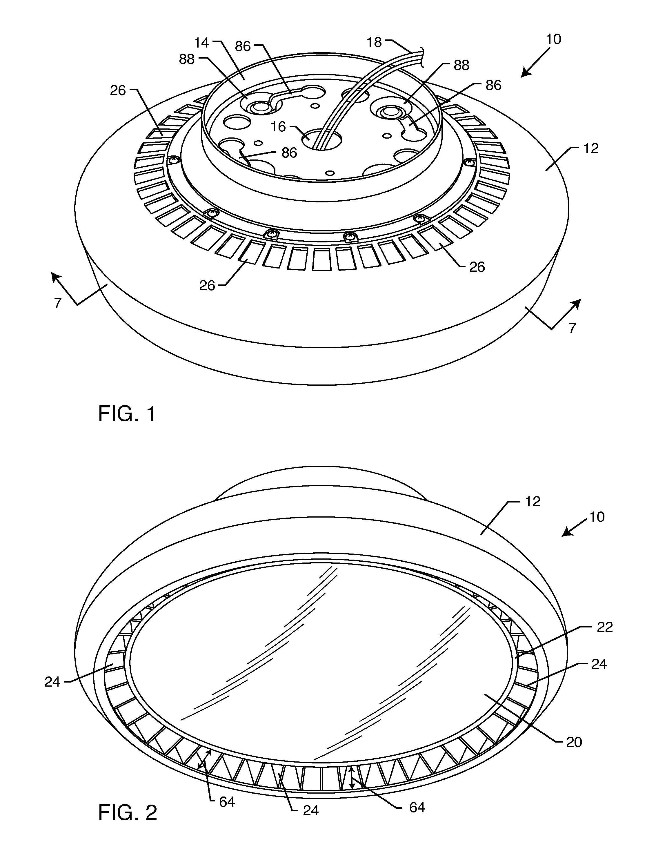
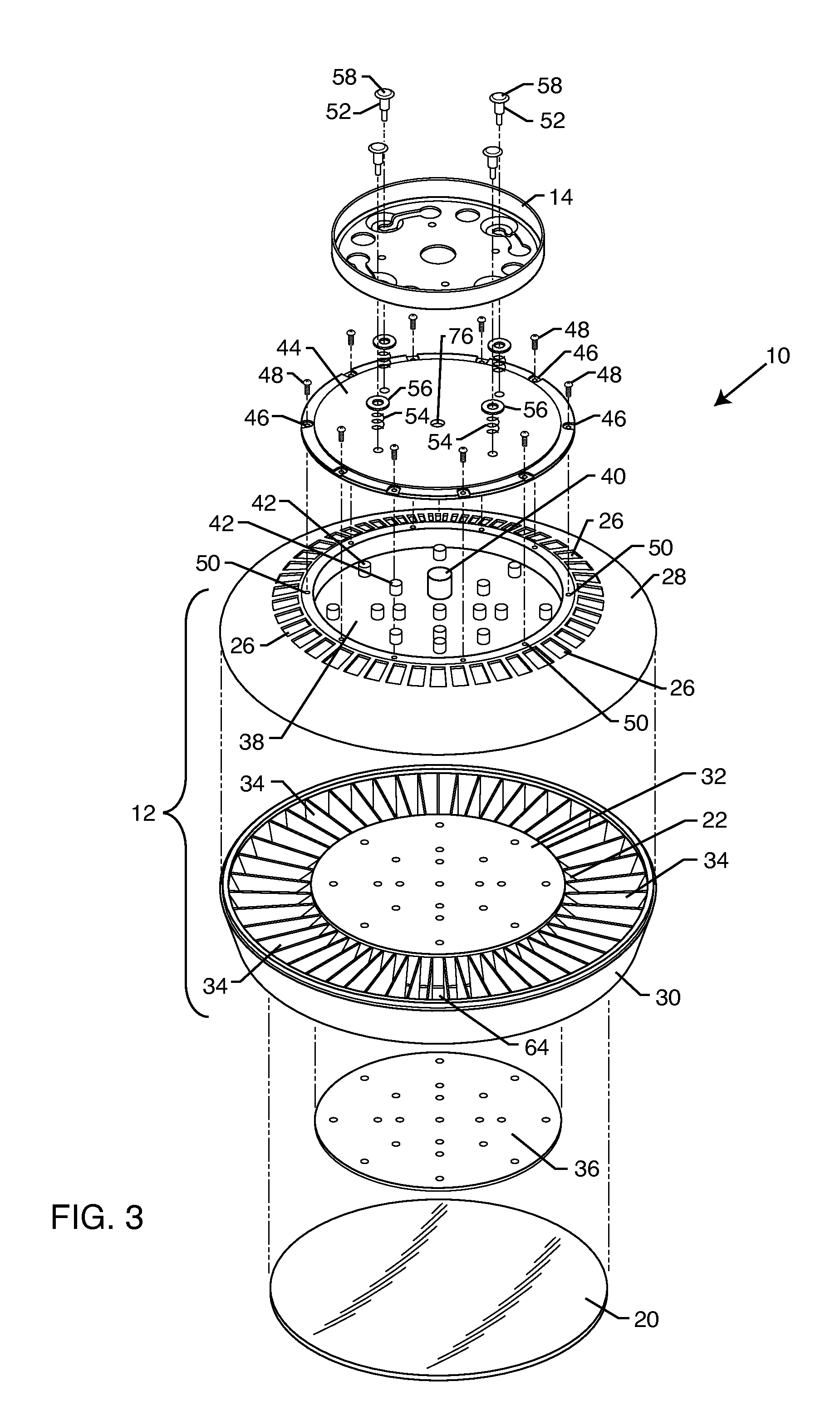
As shown in the drawings for purposes of illustration, the present invention for an improved heat sink system is illustrated embodied in an industrial light, referred to generally by the reference number 10. In FIG. 1, the industrial light 10 is illustrated having an outer heat sink 12 coupled to a mounting bracket 14 through a snap and turn mounting system. The mounting bracket 14 includes a central aperture 16 providing access to the interior of the industrial light 10. As shown in FIG. 1, a pair of electrical wires 18 extend out from within the outer heat sink 12 and the mounting bracket 14 to provide electrical energy to a device located within the interior of the outer heat sink 12. Positioning the central aperture 16 to the interior of the mounting bracket 14 ensures that the industrial light 10 can be attached to the mounting bracket 14 via the aforementioned snap and turn mounting system without the electrical wires 18 binding, twisting or otherwise getting caught on compone...


PUM


Abstract

The improved heat sink system for a lighting fixture includes a conductive mount configured to selectively receive and retain a lighting subassembly. An inner heat sink couples to the conductive mount and is positioned to encompass the lighting assembly. A plurality of cooling fins couple to and extend away from the inner heat sink. An outer heat sink couples to the cooling fins and is offset from the inner heat sink to permit air flow therebetween and over the cooling fins. This enables air convection cooling of the inner heat sink, the outer heat sink and the cooling fins simultaneously to draw heat energy away from the lighting subassembly.

Description

BACKGROUND OF THE INVENTIONThe present invention relates to an improved heat sink system. More particularly, the invention relates to an improved heat sink system having an inner heat sink coupled to a plurality of outwardly extending cooling fins encased by an outer heat sink, thereby improving heat dissipation from a heat generating device by increasing the amount of heat sink surface area subject to air convection.Heat sinks are components or assemblies designed to transfer energy away from a device generating heat. Oftentimes, heat sinks make use of a fluid medium such as water or air to facilitate heat exchange to the surrounding environment. Some examples of heat sinks used as a means for heat transfer include refrigeration systems, air conditioning systems, radiators, etc. Other types of heat sinks are used to cool electric devices, such as circuit boards, computer chips, diodes, and other higher powered optoelectronic devices such as lasers and light emitting diodes (LEDs).E...

Claims


Application Information

Patent Timeline
Patent Type & Authority Applications(United States)
IPC IPC(8): H01J13/32F21V1/00F28F13/00F21S4/00
CPCF21V29/004F21S8/03F21V3/049F21V29/83F21Y2105/001F21V29/773F21V17/14F21Y2105/10F21Y2115/10
Inventor TER-HOVHANNISYAN, ZORAK
Owner LIGHT EMITTING DESIGN INC
Why Eureka
Try Eureka