Hospital lighting with solid state emitters

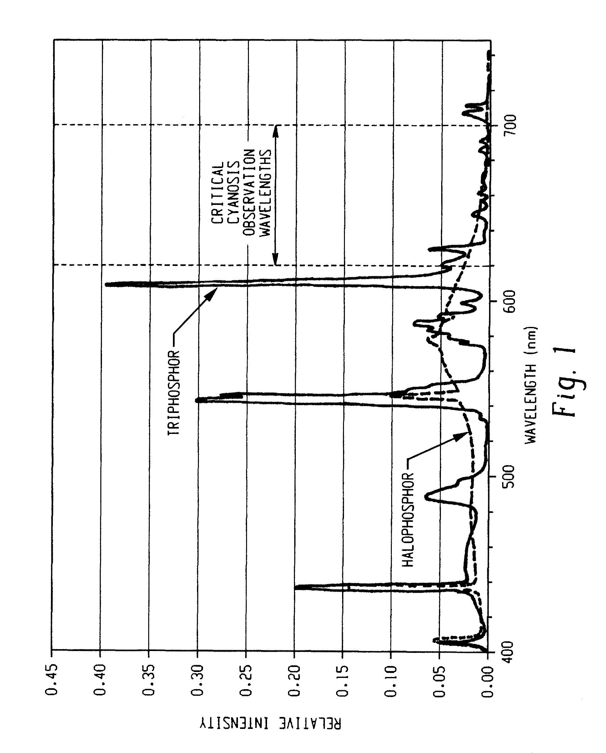
a technology of solid-state emitters and lighting, which is applied in the direction of semiconductor devices for light sources, lighting and heating apparatus, light source combinations, etc., can solve the problems of observable blue discoloration of lips and other mucous membranes, triphosphor lamps are not well suited for this purpose, and skin appears bluish

Active Publication Date: 2011-12-22
GE LIGHTING SOLUTIONS LLC
View PDF0 Cites 47 Cited by
  • Summary
  • Abstract
  • Description
  • Claims
  • Application Information

AI Technical Summary

Benefits of technology

[0016]In an embodiment, a solid-state light emitting-based illumination system is provided which, when energized, exhibits a correlated color temperature (CCT) in the range of between about 3300° K and about 5300° K, and exhibits a COI of less than 3.3. The syste...

Problems solved by technology

Lack of blood oxygenation is an indicator of many potentially harmful medical conditions, some of which may be fatal.
However, when blood is deoxygenated the optical properties of skin distort the dark red color making the skin appear bluish.
Darker blood absorbs more red wavelengths causing a blue-shifting optical effect, and thus oxygen deficiency leads to an observable blue discoloration of the lips and other mucous membranes.
Conversely, if there is an excess of light emitted in this range, the patient will always appear well, giving a false result as well.
It was found that triphosphor lamps are not well suited for this purpose because they have limited emittance in the 600 nm to 700 nm wave...

Method used


Image

  • Hospital lighting with solid state emitters
  • Hospital lighting with solid state emitters
  • Hospital lighting with solid state emitters

Examples


example 1

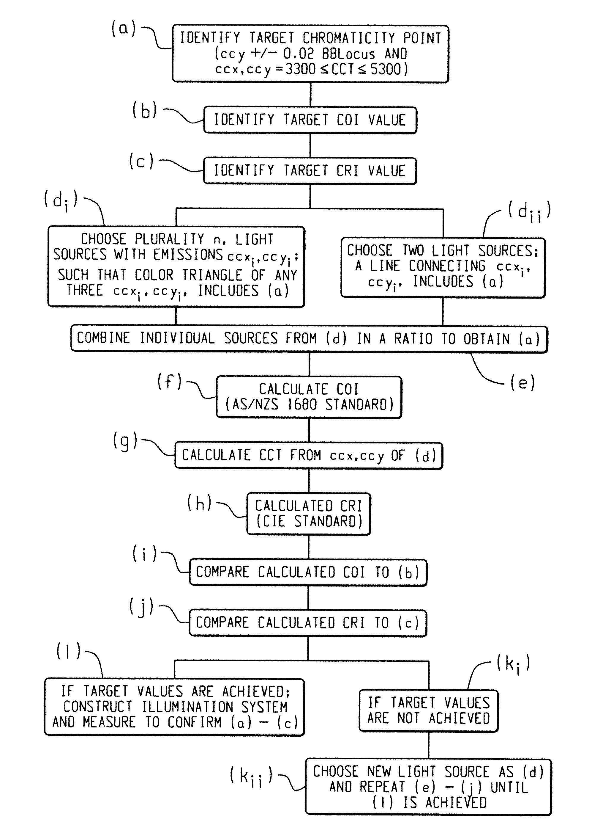
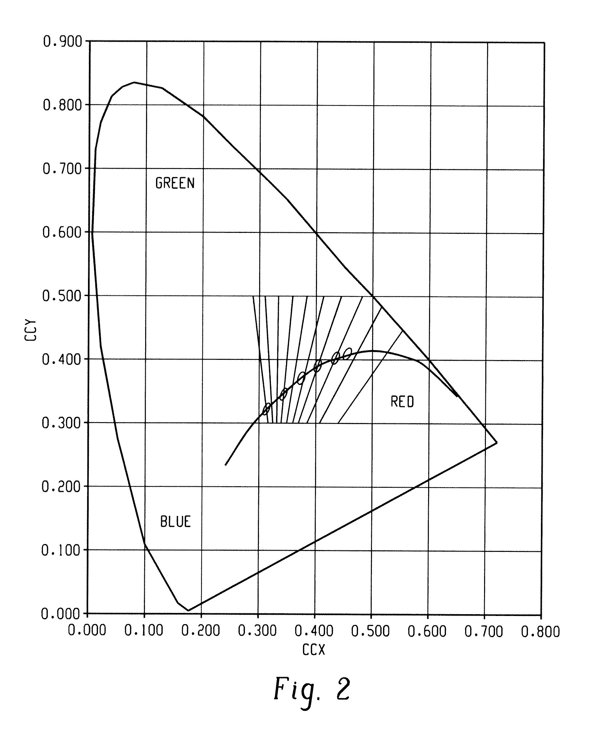
[0049]In this Example 1, an illumination system in accord with an embodiment was created as follows: Two light sources were selected, one emitting at 496.3 nm and the other at 610.5 nm, with Full Width at Half Maximum (FWHM) of about 19 nm, i.e., the peak intensity distribution can be described by a Gaussian distribution with a maximum at the indicated peak wavelength and whose width at one-half of the maximum is about 19 nm. The light was blended to obtain a ccx, ccy in accord herewith, of 0.380, 0.380 which correlates to an ANSI standard 4100K. This selection and blending satisfied steps (a) through (e) of the process, as presented in FIG. 4. The COI was calculated to be 9.51, clearly greater than the target value of 3.3 or lower (Steps f, i). Further, CRI was calculated to be −26, which was also clearly unsatisfactory for purposes of the disclosure (Steps g, j). The FWHM of each peak was adjusted to 60 nm (Step k), following which the peak positions were adjusted to 497.8 nm and ...

example 2

[0050]A second illumination system was created, in keeping with the method set forth above in Example 1, but this time using three light sources. The light sources chosen included one emitting at 466.3 nm, another at 545.5 nm, and the third at 614.1 nm with FWHM of about 24 nm. The ratio of peak intensities was chosen to obtain ccx, ccy coordinates of 0.380, 0.380 (Steps a-e). Using these sources, the COI was calculated to be 3.3, which is the upper limit for this parameter (Step f, i). CRI was also calculated and was 86 (Step g, j). A lower COI was desired. Therefore, peak positions were then adjusted to 462.2 nm, 549.4 nm, and 617.4 nm, respectively (Step jii, k). The ratio of peak intensities was again chosen to obtain ccx,ccy of 0.380, 0.380 (Step e). The COI was then calculated to be 1.7, well below the upper limit of 3.3 (Steps f, i). CRI was calculated to be 80 (Step g, j). FIG. 6a provides the blend spectral distribution for the initial illumination system and 6b provides th...

example 3

[0051]Yet another illumination system was created, again in keeping with the process used in Example 1, however, this example includes the use of spectra of LumiLeds LEDs, available commercially from Philips LumiLeds Lighting Company. This illumination system included 4 light sources, emitting at 461 nm, 535 nm, 594 nm, and 636 nm, with FWHM of about 22, 33, 16 and 18 nm, which is typical of a commercially available product. The ratio of peak intensities was chosen to obtain ccx, ccy of 0.380, 0.380 (Steps a-e). For this system, COI was calculated to be 0.93 (Step f, i), and CRI to be 92 (Step g, j). A fifth source, emitting at 514 nm (FWHM 35 nm), was then added to the illumination system (Step k), and the ratio of peak intensities again chosen to obtain ccx, ccy of 0.380, 0.380 (Step a-e). COI was then recalculated and found to be 1.13 (Steps f, i), and the CRI recalculated to be 94 (Step g, j). At this point, the 461 nm light source was replaced with a 452 nm-emitting light sourc...


PUM


Abstract

A solid state light emitting-based illumination system which, when energized, exhibits a correlated color temperature (CCT) in the range of between about 3300° K and about 5300° K, and exhibits a COI of less than 3.3 is provided. The system comprises two or more solid state elements, and is configured to provide a total light that appears white when energized, the combined light having preselected spectral fraction values such that when combined the emission meets the specified CCT and COI standards. A method for combining individual solid-state light emitters is also provided.

Description

BACKGROUND OF THE DISCLOSURE[0001]The present invention relates to a solid-state illumination system, and more particularly, to a solid-state illumination system for use in hospital or other clinical observation areas. It is to be understood, however, that the invention disclosed herein has utility and application in related areas and with additional lighting systems.[0002]Solid-state lighting provides a potentially higher efficiency light source, as compared to conventional discharge-type lamps, and further provides the capability of adjusting spectral characteristics to obtain specific desirable features. Of particular interest herein is the use of solid-state lighting in clinical observation areas, including hospital examination rooms and other clinical settings, where lighting plays an important role in the observation of skin visual appearance to aid in patient assessment.[0003]Clinical observation is an important aspect of assessing a patient's condition, and the available lig...

Claims


Application Information

Patent Timeline
IPC IPC(8): H05B37/00F21V9/00
CPCF21W2131/208H05B33/086F21Y2113/005F21Y2101/02F21Y2113/13F21Y2115/10H05B45/20
Inventor BEERS, WILLIAM WINDERDUFFY, MARK ELTON
Owner GE LIGHTING SOLUTIONS LLC
Why Eureka
Try Eureka