System and Method for Balancing Voltage of Individual Battery Cells Within a Battery Pack

a battery pack and voltage balancing technology, applied in the direction of battery pack arrangement, transportation and packaging, electrical generators, etc., can solve the problems of reducing battery capacity utilization, unsatisfactory battery cell imbalance, etc., to reduce the peak current capacity, reduce the usable capacity of the battery pack, and limit the current flow within the battery.

Active Publication Date: 2011-12-22
A123 SYSTEMS LLC
View PDF10 Cites 44 Cited by
  • Summary
  • Abstract
  • Description
  • Claims
  • Application Information

AI Technical Summary

Benefits of technology

[0004]By actively balancing charge between battery cells and by controlling the timing of battery cell charging, it may be possible to increase the usable capacity of a battery pack while limiting current flow within the battery. In particular, less instantaneous current may be supplied to battery cells when charge is supplied to different battery cells at different times. For example, rather than charging a first and second battery cell at the same time, the first battery cell can be charged at a first time while the second battery cell is charged at a second time, the first time different than the second time. Since the charging current is supplied at different times, less peak current capacity may be required of a power supply that supplies charge to battery cells.
[0005]The present description may provide several advantages. In particular, the method may reduce peak current demand within a second charging path of a battery pack. In addition, the present method may reduce electrical noise and lower voltage ripple.

Problems solved by technology

Imbalance between battery cells may not be desirable because imbalance may lead to reduced battery capacity utilization.

Method used


Image

  • System and Method for Balancing Voltage of Individual Battery Cells Within a Battery Pack
  • System and Method for Balancing Voltage of Individual Battery Cells Within a Battery Pack
  • System and Method for Balancing Voltage of Individual Battery Cells Within a Battery Pack

Examples


Embodiment Construction

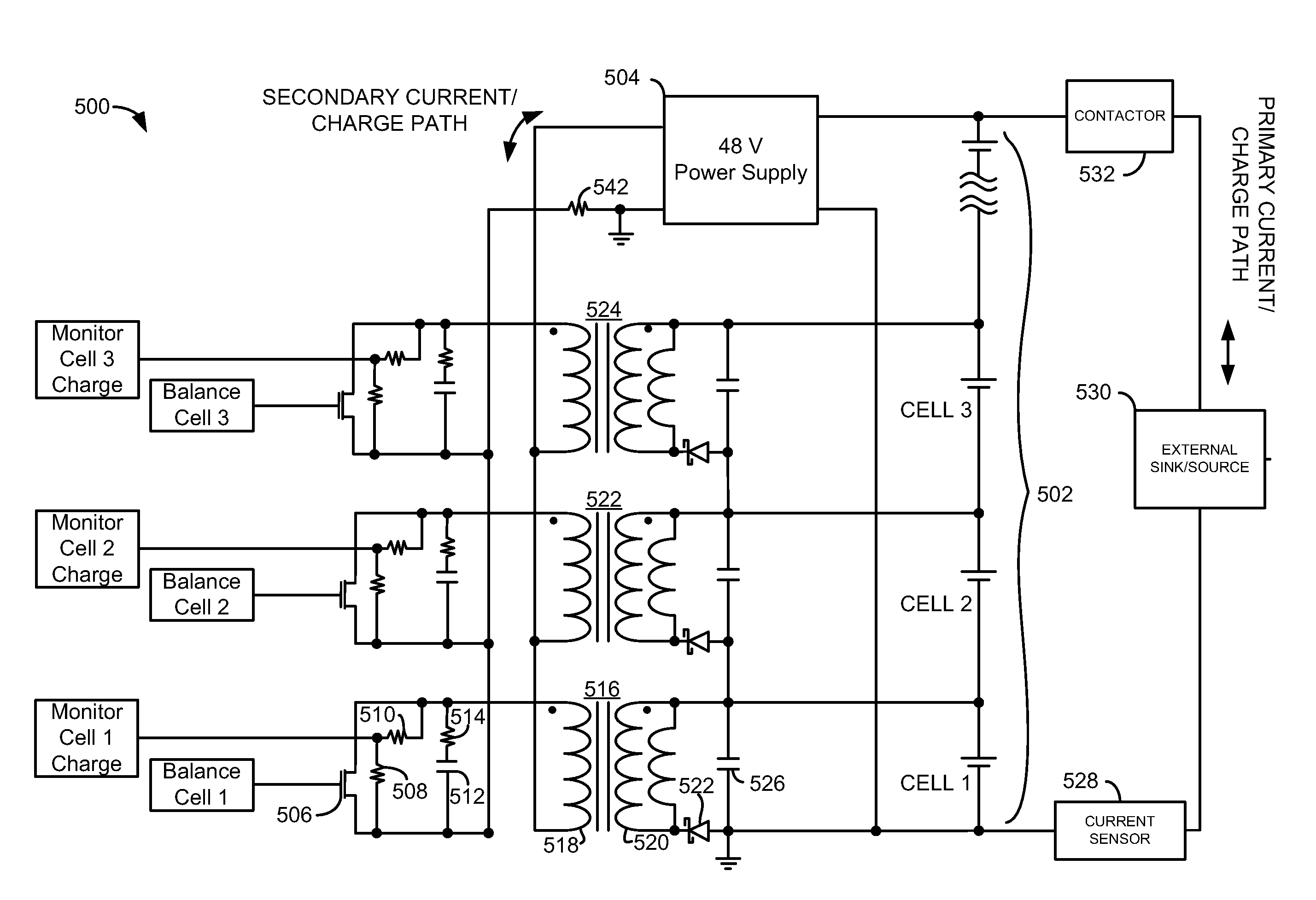
[0024]The present description is related to controlling charge within a battery pack. In one embodiment, battery cells such as those illustrated in FIG. 2 may be combined in a battery pack as illustrated in FIG. 1. The power from the battery cells may be selectively delivered to a load external to the battery pack. Within a battery pack, charge may be shuffled between battery cells by circuitry described in FIGS. 5 and 12. Charge can be shuffled between battery cells according to the methods of FIGS. 6-7 and 13-14 to extend battery discharge cycle duration. Further, charge may be moved within a battery pack according to the methods of FIGS. 8 and 15 to reduce current and electrical noise within a battery pack.

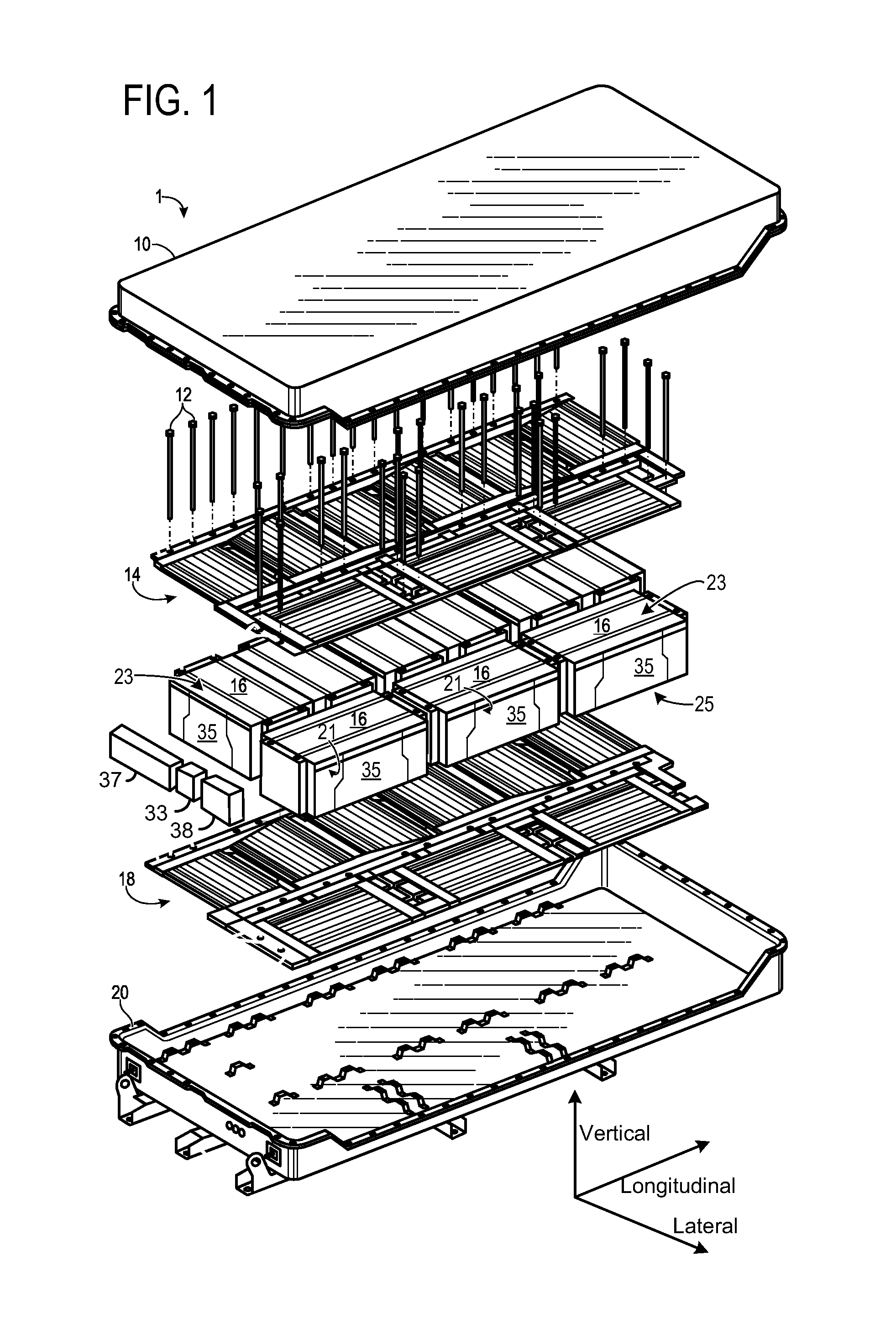
[0025]FIG. 1 shows an exploded view of a battery assembly 1. The battery assembly may include a cover 10, coupling devices 12, a first cooling subsystem 14 (e.g., cold plate), a plurality of battery modules 16, a second cooling subsystem 18 (e.g., cold plate), and a tray 20. Th...


PUM


Abstract

Systems and methods for actively balancing battery cells are disclosed. In one example, a charge is supplied to different battery cells at different times during a battery discharge cycle. The method may reduce instantaneous current draw within a battery pack.

Description

TECHNICAL FIELD[0001]The present description relates to managing balancing of voltages of battery cells within a battery pack. In one example, the battery pack provides power to a vehicle.BACKGROUND AND SUMMARY[0002]Charge variation may occur between battery cells of a battery pack. The charge variation may be related to battery cell manufacturing tolerances, environmental differences within the battery pack, or other factors. Imbalance between battery cells may not be desirable because imbalance may lead to reduced battery capacity utilization. One way to increase battery capacity is to balance charge between battery cells. By balancing or equalizing charge between battery cells, it may be possible for the battery pack to reach a higher charge capacity since all battery cells may be brought to a desired level of charge. For example, charge can be drained from battery cells that achieve an upper voltage limit before other battery cells reach the upper voltage limit. By draining char...

Claims


Application Information

Patent Timeline
Patent Type & Authority Applications(United States)
IPC IPC(8): H02J7/00
CPCH02J7/0014H01M2010/4271H01M10/4207Y02E60/10
Inventor FIREHAMMER, PAUL W.SINSHEIMER, BENJAMIN
Owner A123 SYSTEMS LLC
Why Eureka
Try Eureka