Reflector antenna including radome

a technology of reflector antenna and radome, which is applied in the direction of waveguide type devices, radio element housings, electrical devices, etc., can solve the problems of difficult to manufacture the antenna using tolerances, difficult to couple energy from rectangular wave guides, and high manufacturing costs of millimeter wave antenna designs

Inactive Publication Date: 2011-12-22
SIKLU COMM
View PDF2 Cites 22 Cited by
  • Summary
  • Abstract
  • Description
  • Claims
  • Application Information

AI Technical Summary

Benefits of technology

[0047]using electromagnetic modeling to obtain values for the dimensions which p...

Problems solved by technology

In millimeter wave antenna design one of the issues that is encountered is how to couple energy from a rectangular waveguide to a circular antenna while maintaining high efficiency and suppressing cross-polarization products.
In addition millimeter wave antenna design raises issues of manufacturing cost since the tolerances required are beyond those available from the cheaper mass production techniques.
a. It is difficult to couple energy from a rectangular wave guide to a circular antenna while maintaining high efficiency and suppressing cross-polarization products
b. It is difficult to manuf...

Method used


Image

  • Reflector antenna including radome
  • Reflector antenna including radome
  • Reflector antenna including radome

Examples


Embodiment Construction

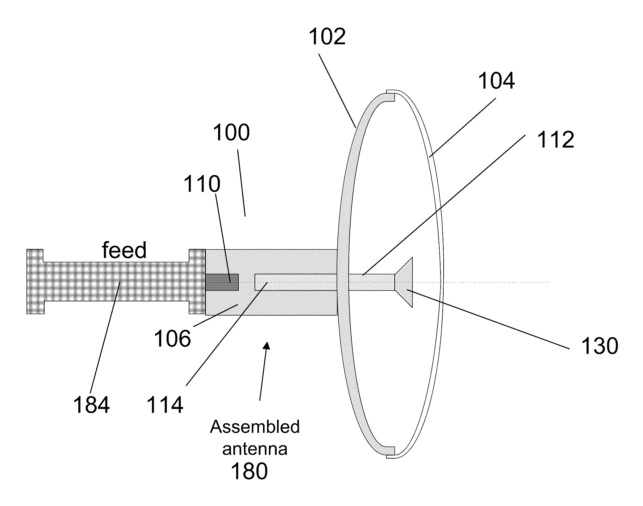
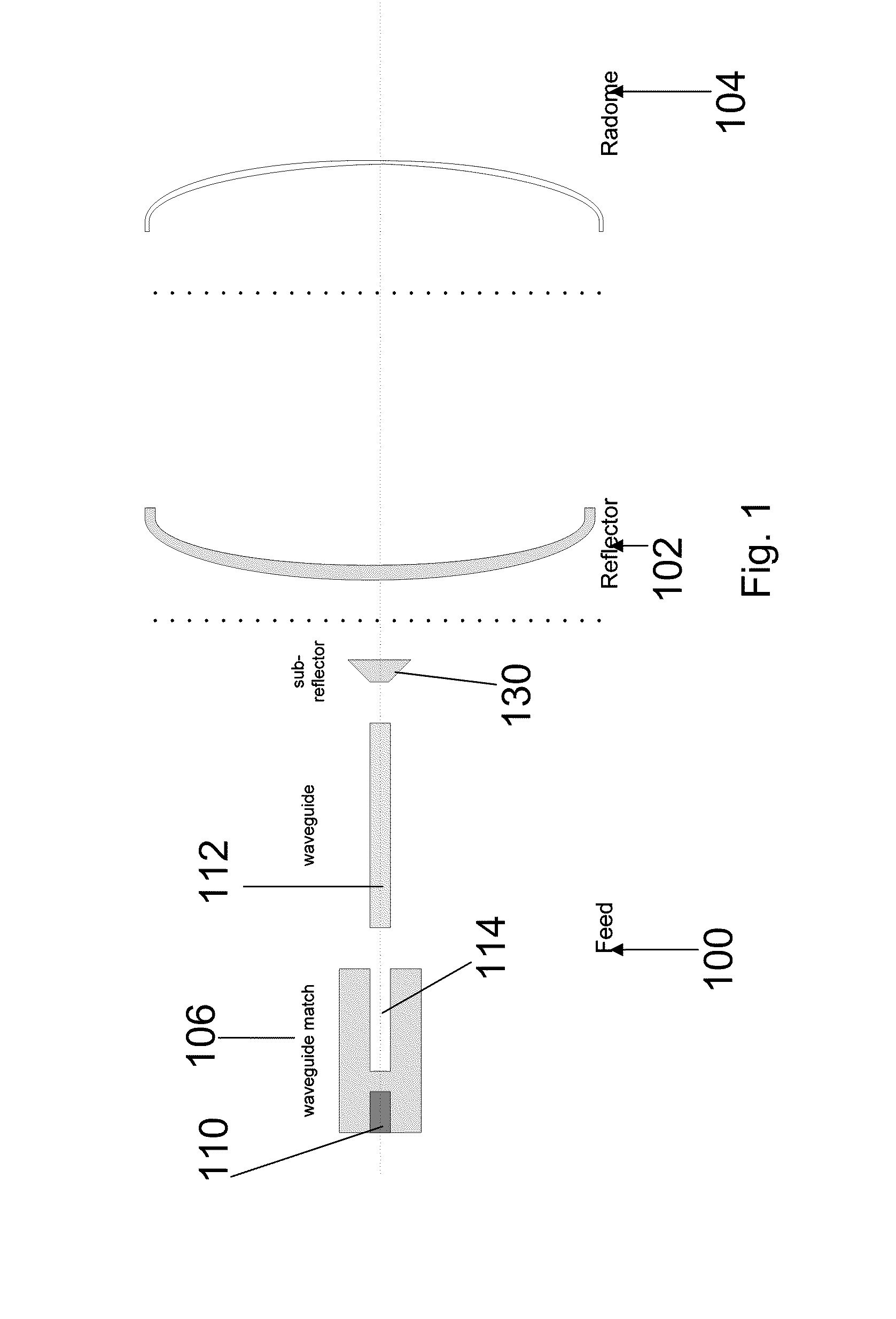
[0079]The present embodiments comprise a reflector antenna and may include an associated radome. In some embodiments, the antenna is for millimeter wavelengths.

[0080]In one embodiment of the present invention the radome differs from a conventional radome in that, instead of being transparent to radiation in all directions, the radome is transparent to radiation in a desired direction or in accordance with a desired directional profile of the beam. The radome thus imposes the desired directional profile on the antenna beam.

[0081]The radiation pattern, or directional profile of the radiation may be enhanced by making parts of the radome of a thickness having an electrical length which is an integer multiple of a half of the transmitted wavelength. Other parts of the radome are of thicknesses whose electrical lengths are not integer multiples thereof. Thus the radome is transparent to the radiation wherever the thickness is an integer multiple and is less transparent wherever the thick...


PUM

PropertyMeasurementUnit
Timeaaaaaaaaaa
Lengthaaaaaaaaaa
Thicknessaaaaaaaaaa

Abstract

A radome comprises a structure covering an antenna, the structure being substantially transparent to radiation of the antenna in a first direction and being less transparent to radiation of the antenna when deviating from the first direction, thereby imparting a directional profile to radiation of the antenna. The millimeter wave antenna structure comprises a sub-reflector lens, and a reflector, the sub-reflector lens in turn comprising a reflecting metal plate and a lens shaped dielectric material, the lens shaped dielectric material and the reflecting metal plate being shaped together to provide a predetermined radiation illumination pattern on the reflector. A waveguide matching holder connects a circular cross section waveguide via a circular cavity, and a rectangular waveguide feed via a rectangular cavity, the rectangular and the circular cavities being shaped to merge into each other.

Description

FIELD AND BACKGROUND OF THE INVENTION[0001]The present invention relates to a reflector antenna, and / or an associated radome and, more particularly, but not exclusively to such an antenna for millimeter wavelengths.[0002]In millimeter wave antenna design one of the issues that is encountered is how to couple energy from a rectangular waveguide to a circular antenna while maintaining high efficiency and suppressing cross-polarization products.[0003]In addition millimeter wave antenna design raises issues of manufacturing cost since the tolerances required are beyond those available from the cheaper mass production techniques.[0004]Furthermore regulations require a certain directivity profile of the beam so as to suppress unwanted interference.[0005]Antennas often include a radome. A radome (a portmanteau of the words radar and dome) is a structure that forms a weatherproof enclosure that protects a microwave or radar antenna. The radome is constructed of material that minimally atten...

Claims


Application Information

Patent Timeline
IPC IPC(8): H01Q19/10H01P11/00H01Q19/06H01Q13/00H01Q1/42
CPCH01Q1/42H01Q13/00H01Q15/08Y10T29/49016H01Q19/00H01Q19/06H01Q19/193H01Q15/16
Inventor HALUBA, OVADIALEIBA, YIGAL
Owner SIKLU COMM
Why Eureka
Try Eureka