
Ink discharge apparatus

Active Publication Date: 2011-12-22
BROTHER KOGYO KK
View PDF9 Cites 2 Cited by
  • Summary
  • Abstract
  • Description
  • Claims
  • Application Information

AI Technical Summary

Benefits of technology

[0011]An object of the preset teaching is to provide an ink discharge apparatus capable of suppressing the adhesion of the deep color ink to the light color nozzles and preventing the light color nozzles from being dirties by the deep color ink in a structure in which the cap member (suction cap member) is configured to be rockable for the purpose of tolerating the variation in the install position of the nozzle surface.
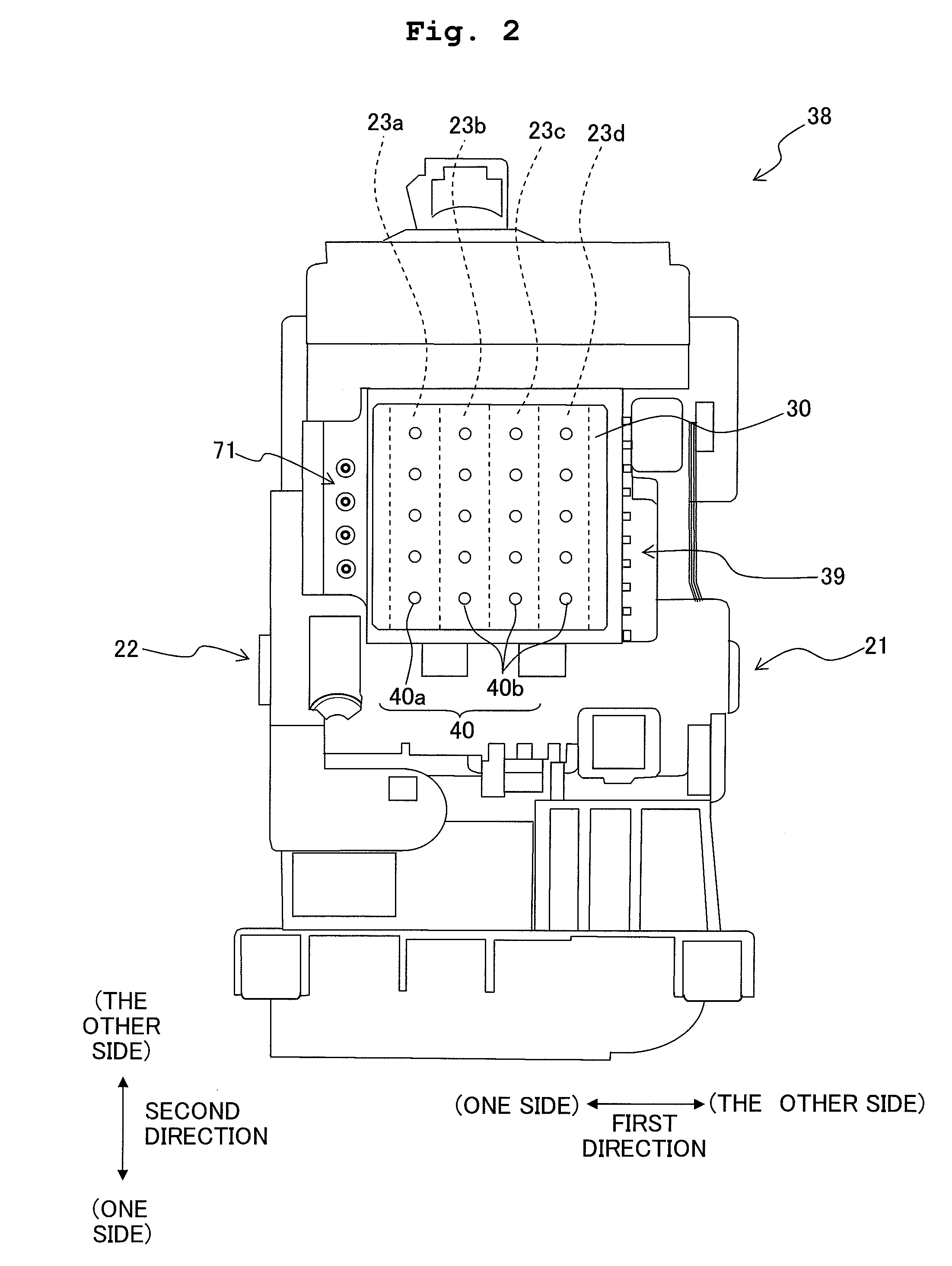
[0023]In view of such a situation, in the ink discharge apparatus of the present teaching, the urging mechanism urges the suction cap in the orthogonal direction at the corner portion, of the suction cap, which is positioned in the suction cap at a portion of the first ink chamber, the portion being located on the opposite side opposite to the second ink chamber in the first direction and is located in the suction cap on the one side in the second direction. By urging the corner portion, of the first ink chamber, located on the opposite side opposite to the second ink chamber, the suction cap is inclined, while the suction cap is being separated away from the nozzle surface, so that a portion, of the suction cap, on the side of the second ink chamber is separated and away from the nozzle surface by a greater distance than another portion, of the suction cap, on the side of the first ink chamber. With this, even if the ink flows or moves over the partition wall, it is possible to make the first ink having the light color inflow (enter) into the second ink chamber, rather than the second ink having the deep color inflowing into the first ink chamber as described above. As a result, even when the first ink flows into and mixes with the second ink, the influence on the tint or color of the second ink is small than in a case that the second ink flows into and mixes with the first ink, thereby making it possible to suppress the influence on the tint or color of the ink to be considerably small. Therefore, it is possible to suppress the adhesion of the second ink to the first nozzle and prevent the first nozzle from being dirtied.
[0024]According to the present teaching, in the structure in which the cap body (cap member) is configured to be rockable to tolerate the variation in the install position of the nozzle surface, it is possible to suppress the adhesion of the second ink having the deep color to the first nozzle and suppress the dirtiness of the first nozzle due to the second ink.

Problems solved by technology

However, in a case that the suction cap is constructed to be three-dimensionally rockable, there is a fear that the ink might flow out of a cap chamber over the partition wall and inflow (enter) into another ink chamber adjacent to the cap chamber and mix with the ink in the adjacent cap chamber.
In this situation, for example, if the deep color ink inflows into the light color ink chamber, the inside of the light color ink chamber is dirtied (stained) by the deep color ink.
Such a dirtiness in the light color ink chamber cannot be completely removed by the suction alone.
As a result, when the suction purge process is again performed in a state that the inside of the cap chamber (light color ink chamber) is dirtied by the deep color ink, there is a fear that the dirtied suction cap might be brought into contact with the nozzle surface, which in turn causes the deep color ink to adhere to the light color nozzles, thereby dirtying the light color nozzles.

Method used


Image

  • Ink discharge apparatus
  • Ink discharge apparatus
  • Ink discharge apparatus

Examples


Embodiment Construction

[0035]In the following, an embodiment of the present teaching will be explained with reference to the drawings. In this embodiment, the present teaching is applied to a printer which performs printing of a desired text (letter) and / or a desired image on a recording paper (recording sheet) by jetting (discharging) an ink from a discharge head onto the recording paper.

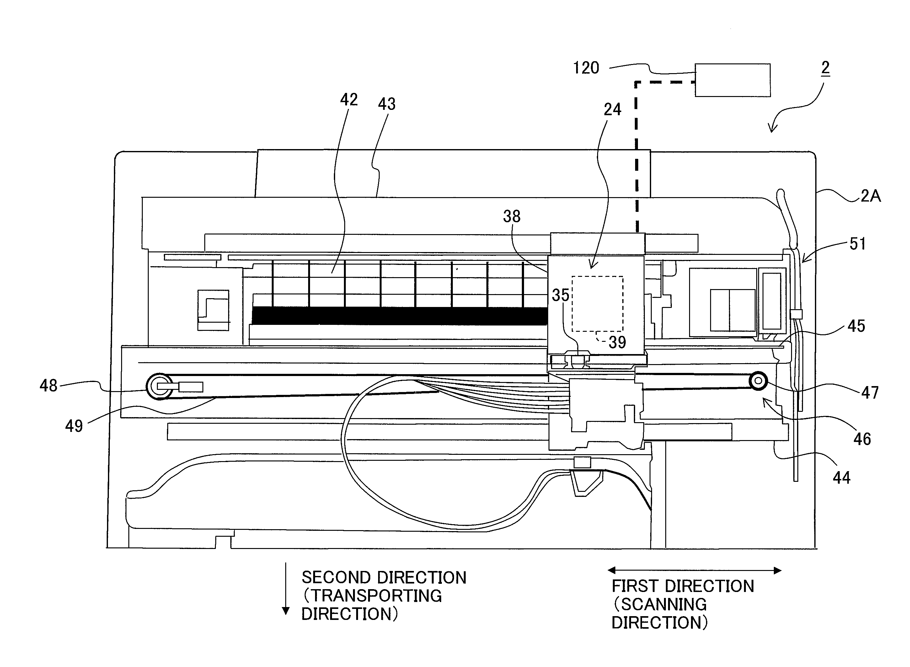
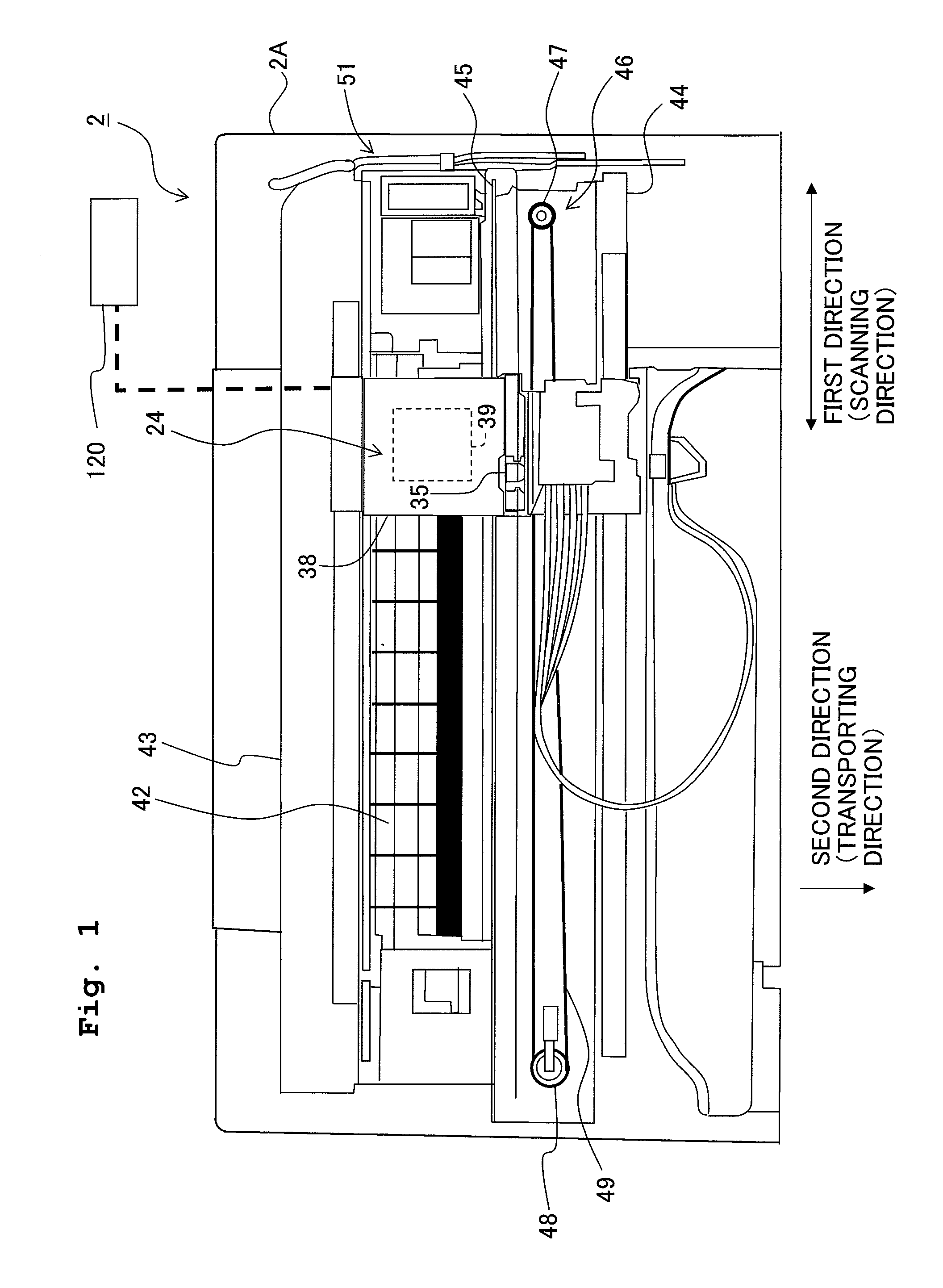
[0036]With reference to FIG. 1, an explanation will be given about the schematic construction of a printer 2 as an embodiment of the ink discharge apparatus of the present teaching.

[0037]The printer 2 has an apparatus body 2A which is provided with a printing unit 24. The printing unit 24 includes a discharge head 39 of the ink-jet system and a carriage 38 in which the discharge head 39 is provided on a side of the bottom surface of the carriage 38. The carriage 38 is supported to be slidable in a scanning direction (left / right direction in FIG. 1) orthogonal to a transporting direction of the recording paper (direction ...


PUM


Abstract

There is provided an ink discharge apparatus including a discharge head provided with a nozzle surface having a first nozzle which is formed in the nozzle surface and via which a liquid droplet of a first ink is discharged and a second nozzle which is formed in the nozzle surface and via which a liquid droplet of a second ink, having a color deeper than a color of the first ink, is discharged; a maintenance device which performs maintenance of the discharge head; and an apparatus body in which the maintenance device is arranged. The maintenance device includes a suction cap which is arranged with respect to the apparatus body, with a predetermined clearance, so the suction cap is rockable three-dimensionally; and an urging mechanism which urges a corner portion of the suction cap in a direction orthogonal to the nozzle surface.

Description

CROSS REFERENCE TO RELATED APPLICATION[0001]The present application claims priority from Japanese Patent Application No. 2010-138304 filed on June 17, 2010 the disclosure of which is incorporated herein by reference in its entirety.BACKGROUND OF THE INVENTION[0002]1. Field of the Invention[0003]The present invention relates to an ink discharge apparatus which performs printing with respect to a recording medium such as paper (paper sheet) with ink droplets of an ink discharged from a plurality of nozzles provided on a nozzle surface of a discharge head.[0004]2. Description of the Related Art[0005]An ink discharge apparatus has a discharge head provided with a nozzle surface. For example, a plurality of nozzles are disposed on the nozzle surface; and liquid droplets of a deep color ink are jetted from deep color nozzles and liquid droplets of a light color ink are jetted from light color nozzles onto a recording medium such as paper (paper sheet), thereby performing printing on the r...

Claims


Application Information

Patent Timeline
IPC IPC(8): B41J2/165
CPCB41J2/16511
Inventor KATO, YOSHINORI
Owner BROTHER KOGYO KK
Learn More