Optical scanning device and image forming apparatus

a scanning device and image forming technology, applied in the field of optical scanning devices and image forming apparatus, can solve the problems of uneven density in the final image, an increase in the rotational speed, and the failure of the apc to function properly,

Inactive Publication Date: 2011-12-22
RICOH KK
View PDF1 Cites 14 Cited by
  • Summary
  • Abstract
  • Description
  • Claims
  • Application Information

AI Technical Summary

Benefits of technology

[0014]It is an object of the present invention to at least

Problems solved by technology

When a rotary polygon mirror is used in a high-speed optical deflection device, which is necessary to realize a high-speed scanning, for example, limitations exist for an increase in a rotational speed thereof.
However, when the VCSEL is used as a light source unit in an optical scanning device included in an image forming apparatus, an intensity of a scanning beam may be altered by a temperature change or an aging variation to result in an uneven density in a final image (an output image).
However, if the intensity of the monitoring beams received by the monitoring element is not strong enough, the monitoring element cannot detect the intensity accurately and, hence, the APC fails to function properly to make it difficult to maint

Method used


Image

  • Optical scanning device and image forming apparatus
  • Optical scanning device and image forming apparatus
  • Optical scanning device and image forming apparatus

Examples


Embodiment Construction

[0029]Exemplary embodiments of an optical scanning device and an image forming apparatus according to the present invention are described below in greater detail with reference to the accompanying drawings. The present invention is not limited to the embodiments described below, and various changing, such as other embodiments, addition, modification, and deletion, can be made within the scope of the assumption of those skilled in the art. Any one of the aspects is within the spirit and scope of the present invention as long as it has an advantageous effect of the present invention.

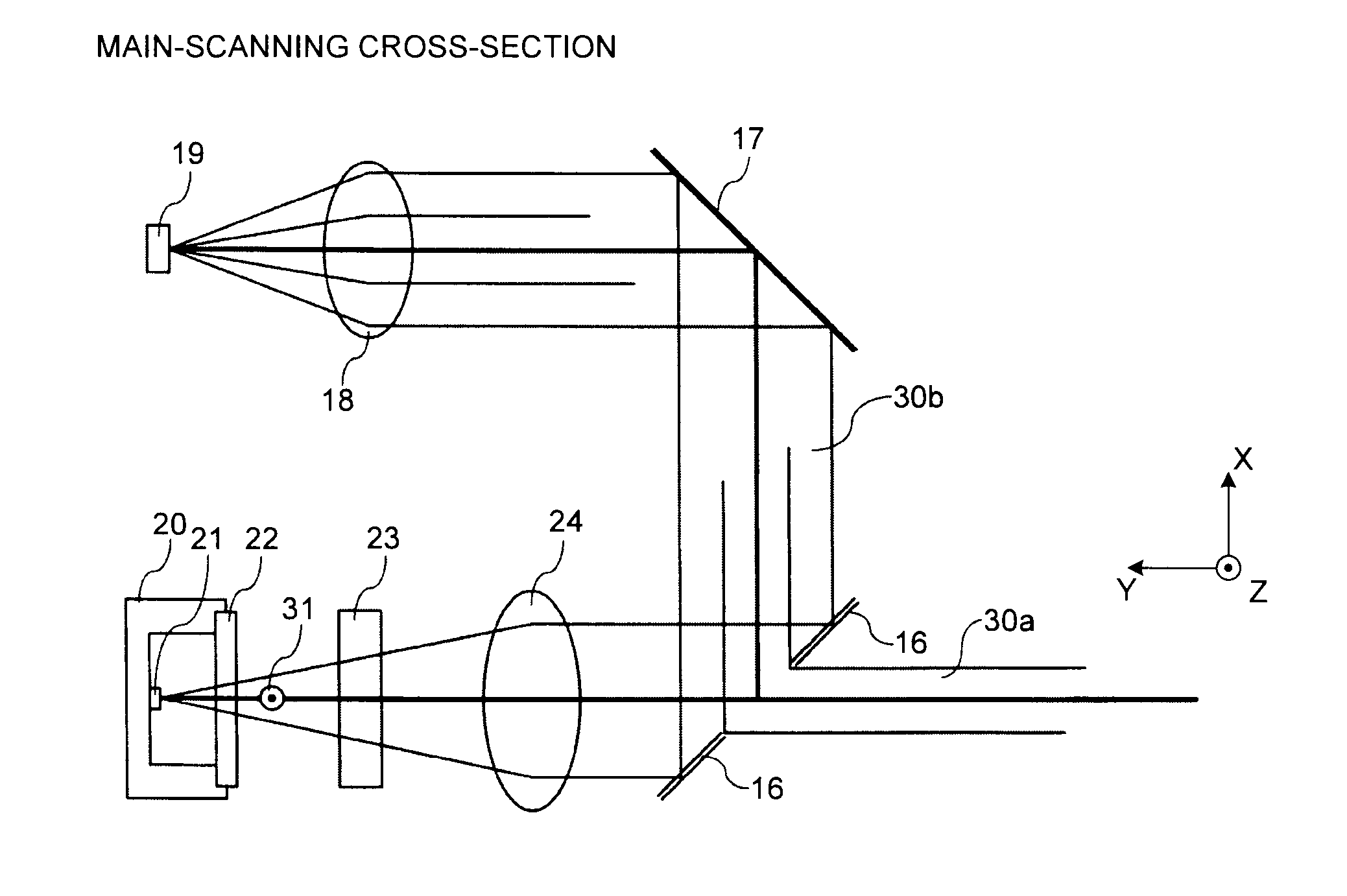
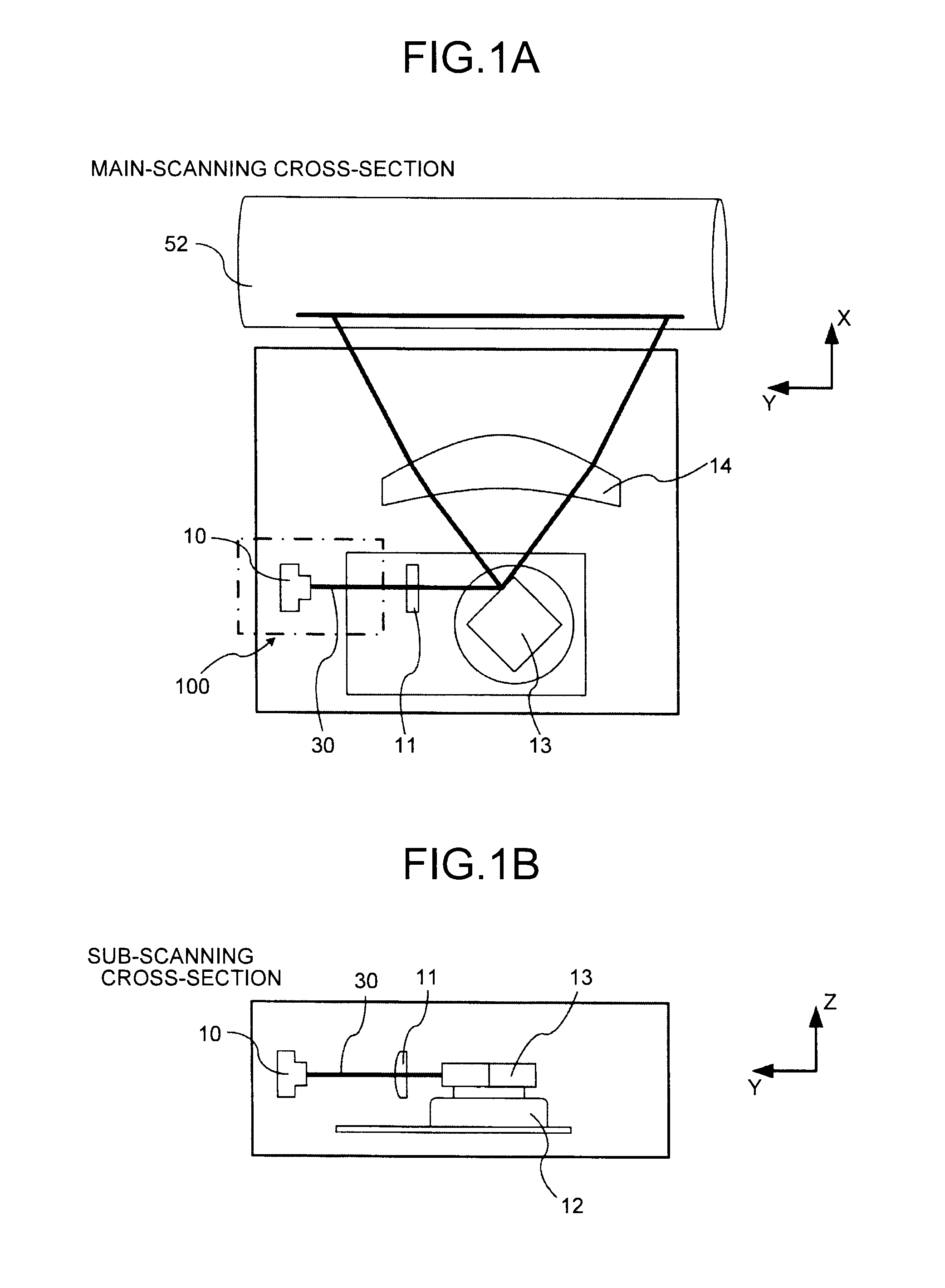
[0030]FIG. 1A illustrates a main-scanning cross-section (X-Y cross-section) of an optical scanning device according to the present invention, and FIG. 1B illustrates a sub-scanning cross-section (Y-Z cross-section) of the optical scanning device. Note that both FIG. 1A and FIG. 1B are depicted in the right-handed coordinate system.

[0031]As illustrated in FIGS. 1A and 1B, laser beam 30 emitted by a light so...


PUM


Abstract

An optical scanning device includes: a light source unit that includes a light emitting unit composed of a laser light source emitting linearly polarized light inside a package member; a deflector that deflects a light beam emitted from the light emitting unit; a pre-deflector optical system arranged on an optical path between the light emitting unit and the deflector; and a scanning optical system that scans a target surface to be scanned with the light beam deflected by the deflector. The pre-deflector optical system includes at least two parallel plate optical elements each composed of a transparent medium having an incident surface and an exit surface parallel to each other. The parallel plate optical elements are arranged to be tilted in inclination that is opposite to each other in a plane of polarization of the linearly polarized light.

Description

CROSS-REFERENCE TO RELATED APPLICATIONS[0001]The present application claims priority to and incorporates by reference the entire contents of Japanese Patent Application No. 2010-138079 filed in Japan on Jun. 17, 2010.BACKGROUND OF THE INVENTION[0002]1. Field of the Invention[0003]The present invention relates to an optical scanning device and an image forming apparatus including the optical scanning device.[0004]2. Description of the Related Art[0005]In recent years, there is an increasing need for an image forming apparatus to have a higher processing speed and a better resolution and, accordingly, it is desired to improve a scanning speed of a scanning unit included therein. When a rotary polygon mirror is used in a high-speed optical deflection device, which is necessary to realize a high-speed scanning, for example, limitations exist for an increase in a rotational speed thereof.[0006]By contrast, an image forming apparatus using a so-called “multi-beam scanning device” has been...

Claims


Application Information

Patent Timeline
IPC IPC(8): G02B26/10
CPCG02B26/105G02B27/28G03G15/0435G03G2215/0404G03G15/04072
Inventor AMADA, TAKUTATSUNO, HIBIKI
Owner RICOH KK
Why Eureka
Try Eureka