Display panel and display device comprising the same

Active Publication Date: 2011-12-22
LG DISPLAY CO LTD
View PDF3 Cites 25 Cited by
  • Summary
  • Abstract
  • Description
  • Claims
  • Application Information

AI Technical Summary

Benefits of technology

[0010]An advantage of the present invention is to provide a display panel and a display device comprising the same, in which a thickness of the display device can be minimized and an electrostatic defect can be prevented from occurring by removing some of a case and/or set cover parts previously regarded as required in related art display products and thereby improving the tolerance against static electricity.
[0011]Additional advantages and features of the invention will be set forth in part in the description which follows and in part will become apparent to those having ordinary skill in the art upon examination of the following or may be learned from practice of the invention. The objectives and other advantages of the invention may be realized and attained by the structure particularly pointed out in the written description and claims hereof as well as the appended drawings.
[0012]To achieve these objects and other advantages and in accordance with the purpose of the invention, as embodied and broadly described herein, a display panel according to an embodiment of the present invention comprises a lower substrate provided with a display area and a non-display area; a plurality of data pad portions formed at one side region of the non-display area; an upper substrate bonded to the lower substrate except the side region of the non-display area; and a ground line supplied with a ground power, and formed on the lower substrate of the non-display area to surround the outline portion of the display area except the data pad portions.
[0013]In another aspect of the present invention, a display device comprises a display unit including a display panel; a guide frame supporting the display unit; and a rear set cover supporting the guide frame, wherein the display panel comprises: a lower substrate provided with a display area and a non-display area, the display area

Problems solved by technology

In those cases, however, there are limitations in reducing the thickness of the display device and developing a new and innovative design for the display device.
As a result, in addition to the lower case and the upper case, the

Method used


Image

  • Display panel and display device comprising the same
  • Display panel and display device comprising the same
  • Display panel and display device comprising the same

Examples


first embodiment

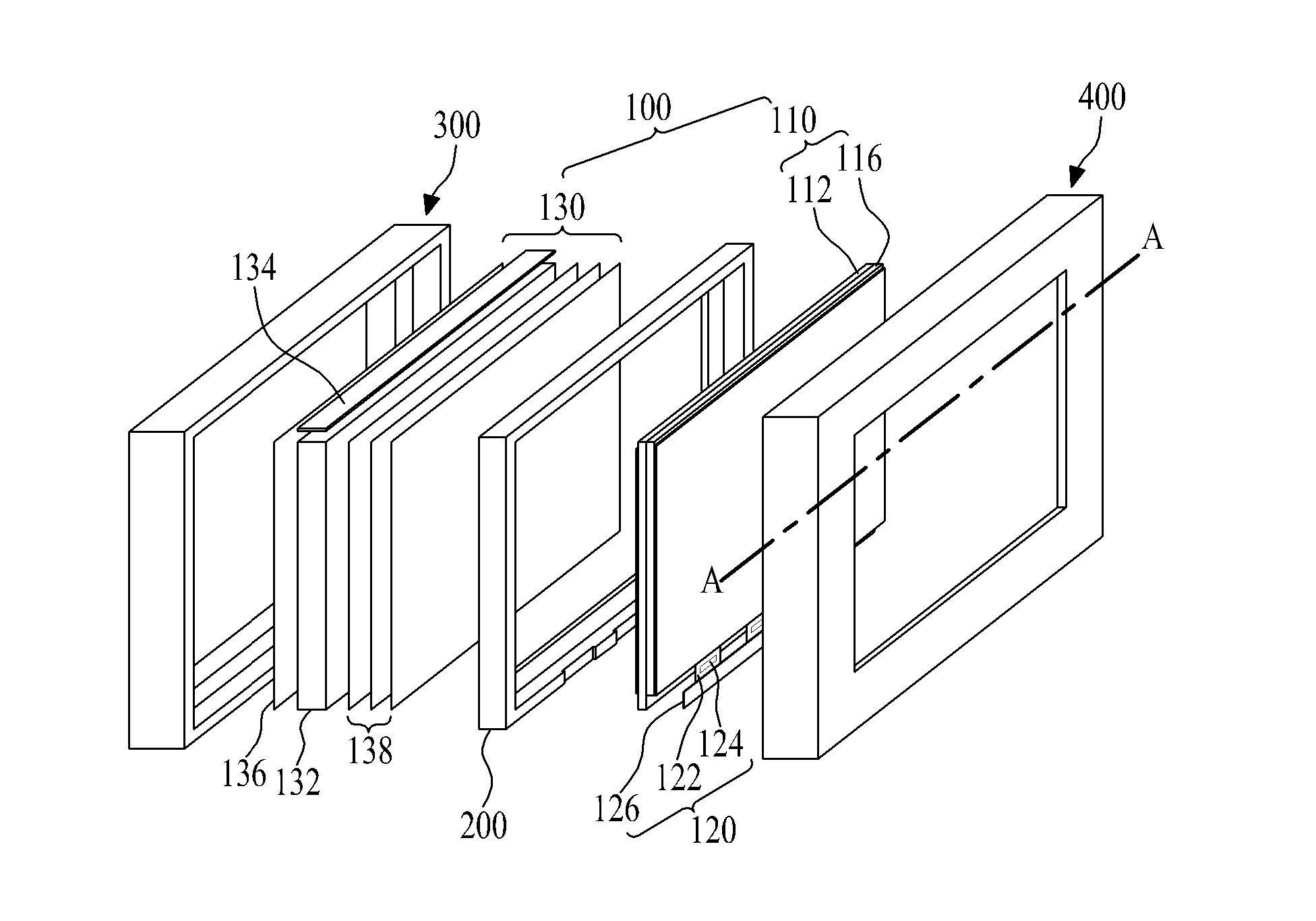
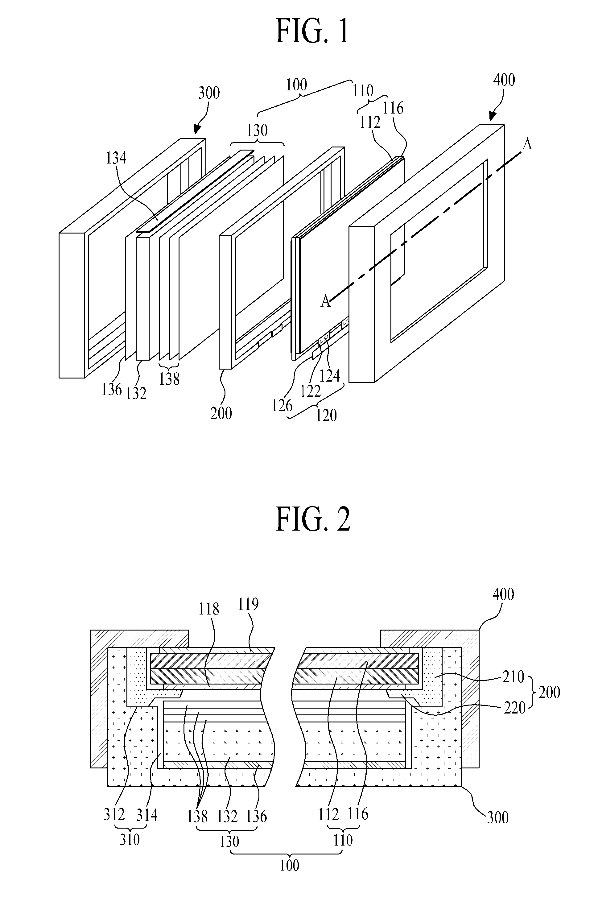
[0026]FIG. 1 is an exploded perspective view illustrating a display device according to the present invention, and FIG. 2 is a sectional view illustrating a section taken along line A-A of FIG. 1.

[0027]Referring to FIGS. 1 and 2, the display device according to the first embodiment of the present invention includes a display unit 100, a guide frame 200, a rear set cover 300, and a front set cover 400. The display unit 100 includes a display panel 110, a panel driver 120, and a back light unit 130. All the components of the display device are operatively coupled and configured.

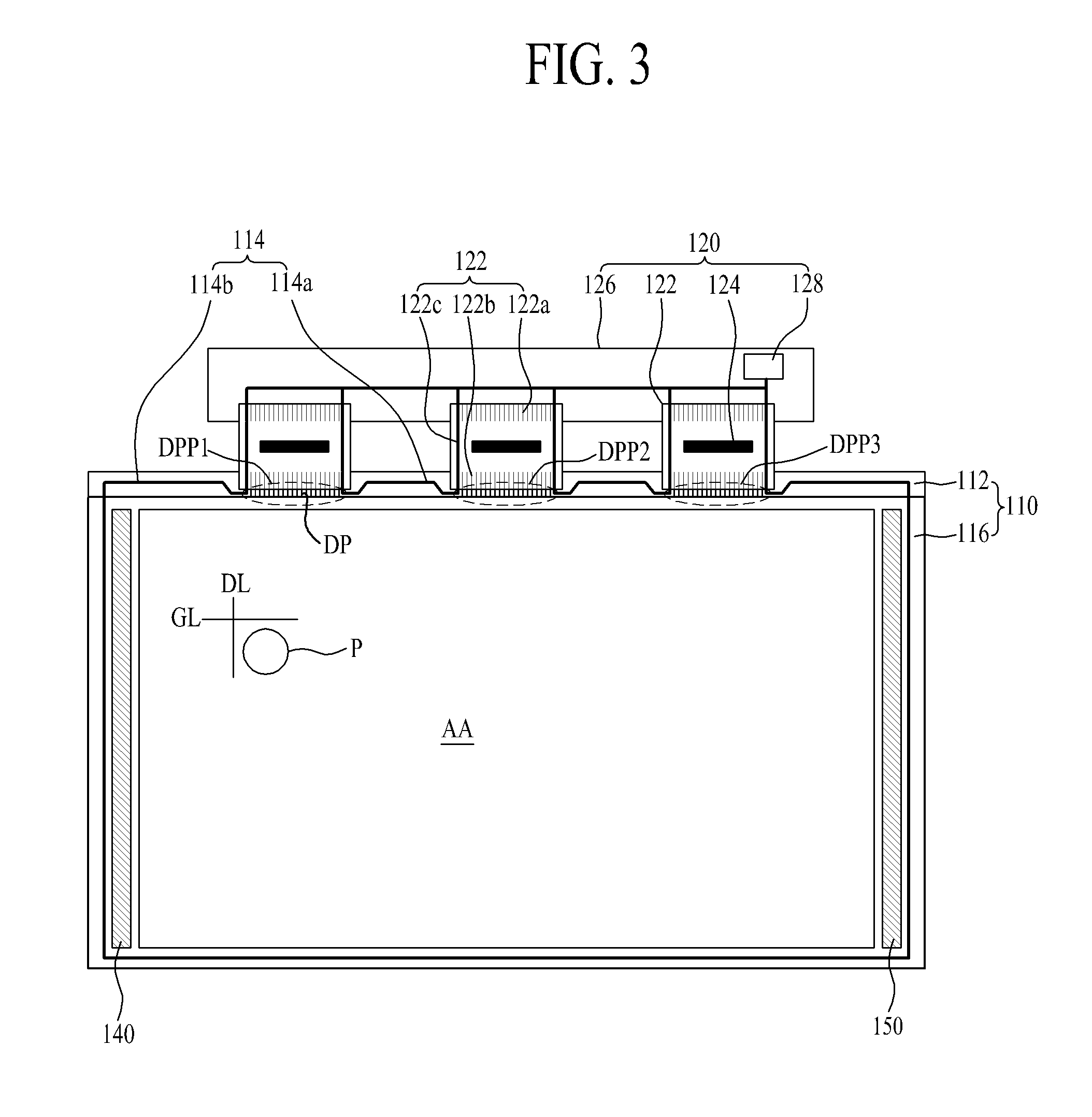
[0028]As shown in FIG. 3, the display panel 110 includes a lower substrate 112, a plurality of data pad portions DPP1, DPP2 and DPP3, a ground line 114, and an upper substrate 116. The lower substrate 112 includes a display area AA (or called as an active area) and a non-display area provided at an outline portion of the display area AA. The non-display area may surround the display area AA.

[0029]Preferably the...

second embodiment

[0066]FIG. 4 is a sectional view illustrating a display device according to the present invention.

[0067]Referring to FIG. 4, the display device according to the second embodiment of the present invention includes a display unit 100, a guide frame 200, and a rear set cover 300. All components of the display device of FIG. 4 are operatively coupled and configured. The display device according to the second embodiment of the present invention is the same as the display device of the first embodiment of the present invention, except that the front set cover 400 is omitted and the guide frame 200 and the rear set cover 300 in FIG. 4 are partially different from those of the first embodiment in their structures. Accordingly, a part of the description of the configuration of the second embodiment, which is the same as that of the first embodiment, is omitted or briefly discussed.

[0068]Referring to FIG. 4, the guide frame 200 is externally exposed to surround the sides of the display panel ...

third embodiment

[0080]For example, as shown in FIG. 5 according to the present invention, the guide frame 200 of the display device surrounds the outer wall of the set sidewall 340 and at the same time surrounds the side of the display panel 110 to form the front edges of the display panel 110, whereby the aesthetic effect of the edge portion of the display device can be improved. For instance, because the outer sides of the display device in FIG. 5 are established entirely by the walls of the guide frame 200, as compared to both the guide frame 200 and the rear set cover 300 as in FIG. 4 for example, the aesthetic aspects of the display device in FIG. 5 may be improved. The display unit 100 in FIG. 5 has the same configuration / structure as the display unit 100 of FIG. 1.


PUM


Abstract

A display panel and a display device having the display panel are discussed. According to an embodiment, the display panel includes a lower substrate provided with a display area and a non-display area; a plurality of data pad portions formed at a side region of the non-display area; an upper substrate bonded to the lower substrate, except for the side region of the non-display area; and at least one ground line supplied with ground power, and formed on the lower substrate of the non-display area to surround in part an outline portion of the display area.

Description

CROSS REFERENCE TO RELATED APPLICATIONS[0001]This application claims the priority benefit of the Korean Patent Application No. 10-2010-0058960 filed on Jun. 22, 2010, which is hereby incorporated by reference for all purposes as if fully set forth herein.BACKGROUND OF THE INVENTION[0002]1. Field of the Invention[0003]The present invention relates to a display device, and more particularly, to a display panel and a display device comprising the same, in which a thickness of the display device can be minimized and an electrostatic defect can be prevented from occurring by removing some of a case and / or set cover parts regarded as necessities of a display product and thereby improving tolerance against static electricity.[0004]2. Discussion of the Related Art[0005]Recently, various flat panel display devices, which can reduce weight and volume acting as disadvantages of a cathode ray tube, have been developed. Although flat panel display devices such as a liquid crystal display device,...

Claims


Application Information

Patent Timeline
IPC IPC(8): H05K7/00
CPCG02F2001/133334G02F1/133308G02F1/133334
Inventor KIM, YOUNG JOE
Owner LG DISPLAY CO LTD
Why Eureka
Try Eureka