Commodity Splitter for an Air Delivery System

Active Publication Date: 2011-12-22
DEERE & CO
View PDF7 Cites 31 Cited by
  • Summary
  • Abstract
  • Description
  • Claims
  • Application Information

AI Technical Summary

Benefits of technology

[0004]A compact three-way commodity splitter is mounted horizontally on a folding implement and provides a more streamlined mounting appearance. The splitter is easier to mount on the implement frame, and multiple spli

Problems solved by technology

Commodity carts are limited in the number of metered or primary runs for distributing product by an air conveyance method.
The air towers extend vertically and can present interference problems on a folding implement because of space constraints.
Connecting the vertical tower to the implement frame can be difficult.
Such rout

Method used


Image

  • Commodity Splitter for an Air Delivery System
  • Commodity Splitter for an Air Delivery System
  • Commodity Splitter for an Air Delivery System

Examples


Example

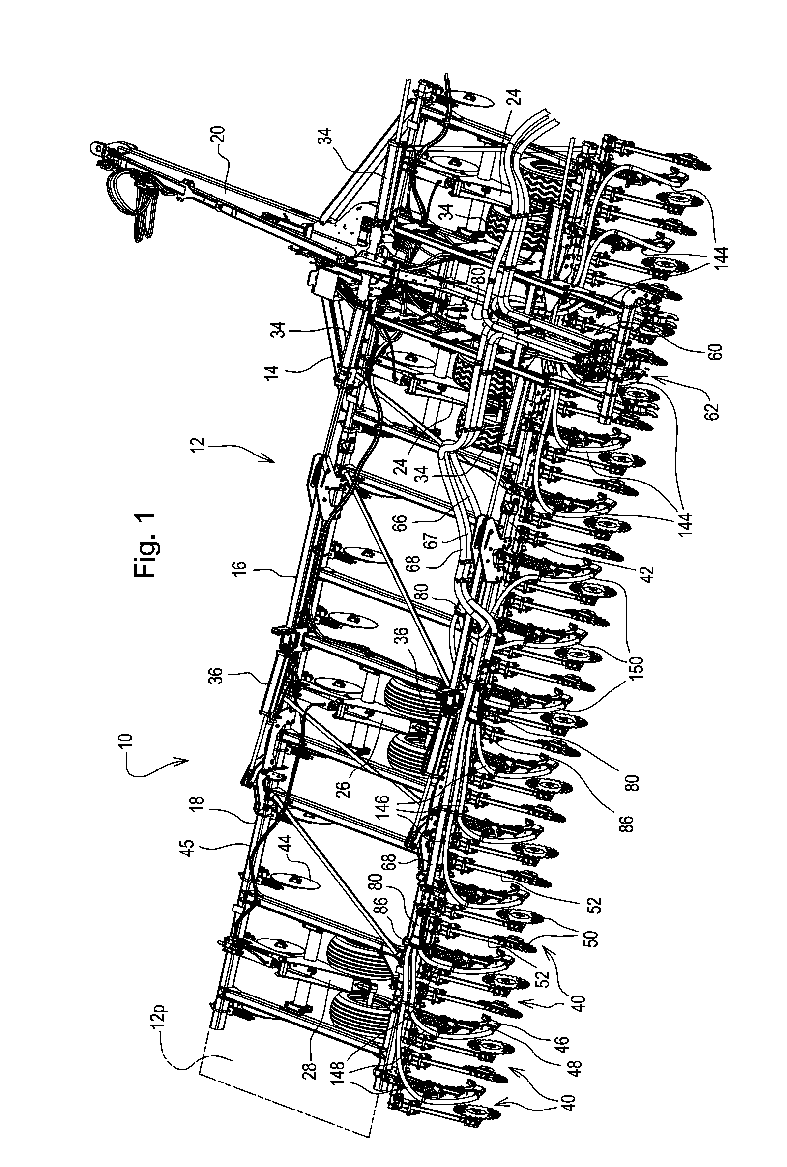
[0020]Referring to FIG. 1 therein is shown a portion of a soil treatment implement 10 having a rectangular main frame 12 which includes a center section 14, an inboard wing section 16 hinged to the center section 14, and an outboard wing section 18 hinged to the center section 16. The right side of the implement 10 is generally the mirror image of the left side shown in FIG. 1. A central towing hitch 20 is connected to the front of the center section 14, and lift wheel assemblies 24, 26 and 28 support the frame 12 for forward movement over the ground.

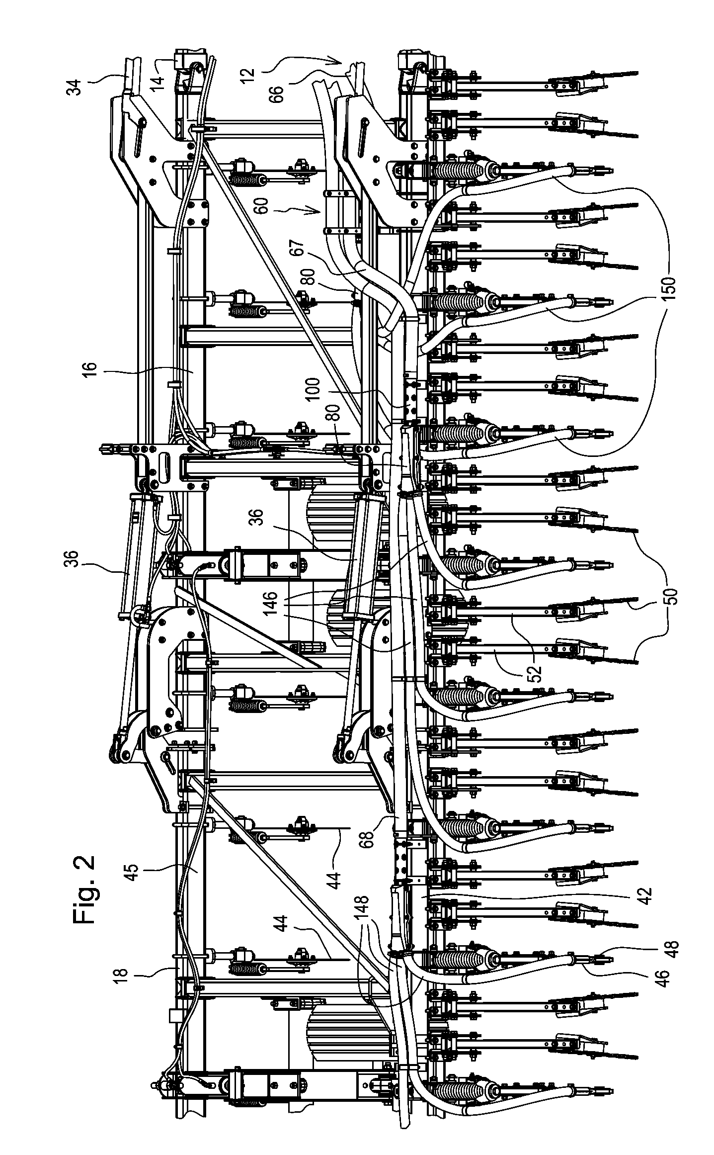
[0021]Folding cylinders 34 and 36 pivot the wing sections 16 and 18 about fore-and-aft extending pivotal axes between an unfolded frame field-working position (shown) and a folded frame field-working position. In the folded position, the outboard wing sections 18 are folded adjacent each other and then lifted over the center section 14.

[0022]Commodity delivery tools indicated at 40 are spaced transversely along rear main frame tube stru...


PUM


Abstract

A commodity splitter (80) for granular agricultural material includes a chamber (84) with an input port (92) and multiple output ports (94, 96, 98), the chamber (84) having first and second walls (110,112) and upright diverting fins (114, 116) connected to and extending from the first horizontal wall (110) towards the second wall (112). The fins (114, 116) terminate in longitudinal edges (114e, 116e) offset from the second wall (112) to form material directing channels (94c, 96c, 98c) of similar cross-sections for directing an amount of the entrained material to each of the multiple outputs (94, 96, 98). The surfaces of the fins (114, 116) mechanically divert material not fully entrained in the air flow and break clumps. A blockage preventing and pressure-equalizing open area (129) is defined within the chamber (84) to allow passage of material clumps and to equalize pressure in the material directing channels (94c, 96c, 98c) for uniform commodity flow.

Description

FIELD OF THE INVENTION[0001]The present invention relates generally to air delivery of particulate matter and, more specifically, to a splitter for dividing a flow of agricultural particulate material from a single conduit to multiple conduits.BACKGROUND OF THE INVENTION[0002]Commodity carts are limited in the number of metered or primary runs for distributing product by an air conveyance method. Air towers mounted on the implement are commonly used to divide each primary run in to numerous secondary runs which extend to ground-engaging tools for distributing the product to the ground. The air towers extend vertically and can present interference problems on a folding implement because of space constraints. Connecting the vertical tower to the implement frame can be difficult. The air tower design often requires the secondary hoses which connect to the upper end of the tower in a radial pattern to extend vertically and bend sharply to reach the desired location for product placement...

Claims


Application Information

Patent Timeline
IPC IPC(8): B65G53/52
CPCA01C7/082B65G53/528A01C7/084
Inventor JOST, BRIAN PATRICKRIEWERTS, PAUL R.CASPER, ROBERT T.
Owner DEERE & CO
Why Eureka
Try Eureka