Method and system for adjusting the flow rate of charge material in a charging process of a shaft furnace

Active Publication Date: 2011-12-22
PAUL WURTH SA
View PDF8 Cites 5 Cited by
  • Summary
  • Abstract
  • Description
  • Claims
  • Application Information

AI Technical Summary

Benefits of technology

[0016]In other words, a valve characteristic specific to each batch (and each control valve) is provided and corrected as often as required in function of the actual flow rate at which an instance of the batch in question was discharged. These specific valve characteristics are thus caused to match more and more closely the true valve characteristic that applies to the discharge of the batch in question. They thereby adapt automatically to any batch-inherent properties that influence the flow rate (material mixtures, granularity, total weight, humidity, . . . ) during discharge. Using valve settings derived from the progressively corrected specific valve characteristics will thus gradually adjust the flow rate to the desired flow rate setpoint. Moreover, as opposed to known adjustment methods, in which flow rate control for different batches of the same material type in a charging cycle relies on one and the same predetermined valve characteristic for this material type, the proposed method automatically adapts to differences in the top charging parameters of different batches of the same type, for instance to closure of the flow control valve between different chute pivoting positions. As will be appreciated, compared to the known approach of providing only a limited number of characteristics for each different type of material (e.g. agglomerated fines, coke, pellets, or ore) respectively, the presently proposed solution is particularly beneficial when charging one or more batches that comprise a mixture of different material types.
[0017]A corresponding system for adjusting the flow rate is proposed in claim 7. In accordance with the invention, the system mainly comprises memory means storing the specific valve characteristics and a suitable programmable computing means (e.g. a computer or PLC) programmed to perform the key aspects of the proposed method as itemized above.

Problems solved by technology

Despite its obvious benefits regarding circumferentially uniform weight distribution, this approach leaves room for improvement, among others because it requires a rather complex control system.
Moreover, it has been found that known approaches are not sufficiently adaptive and, under certain circumstances, may lead to unsatisfactory results, especially in case of variations in batch properties and in case of batches consisting of a mixture of different charge materials.

Method used


Image

  • Method and system for adjusting the flow rate of charge material in a charging process of a shaft furnace
  • Method and system for adjusting the flow rate of charge material in a charging process of a shaft furnace
  • Method and system for adjusting the flow rate of charge material in a charging process of a shaft furnace

Examples


Embodiment Construction

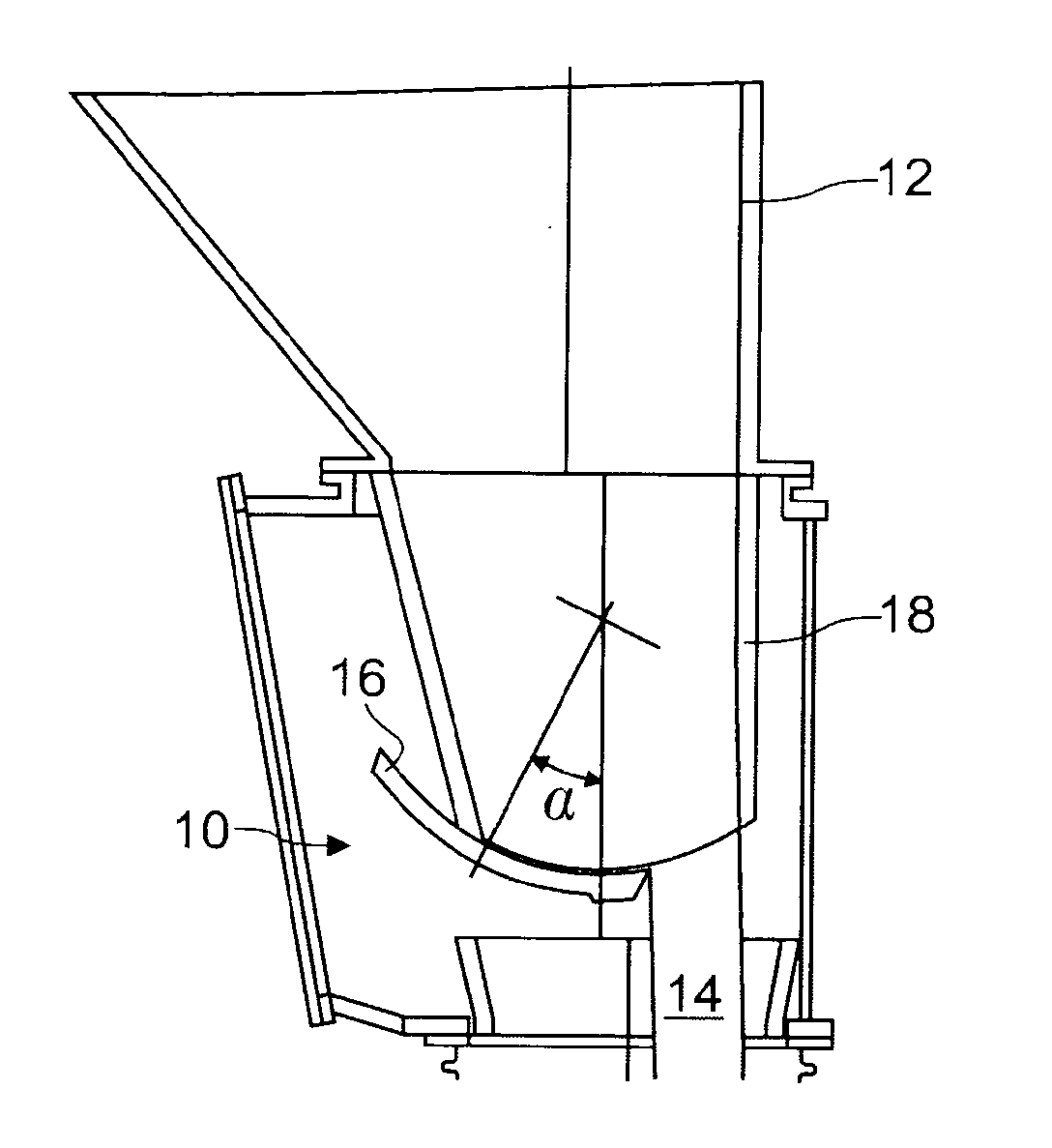
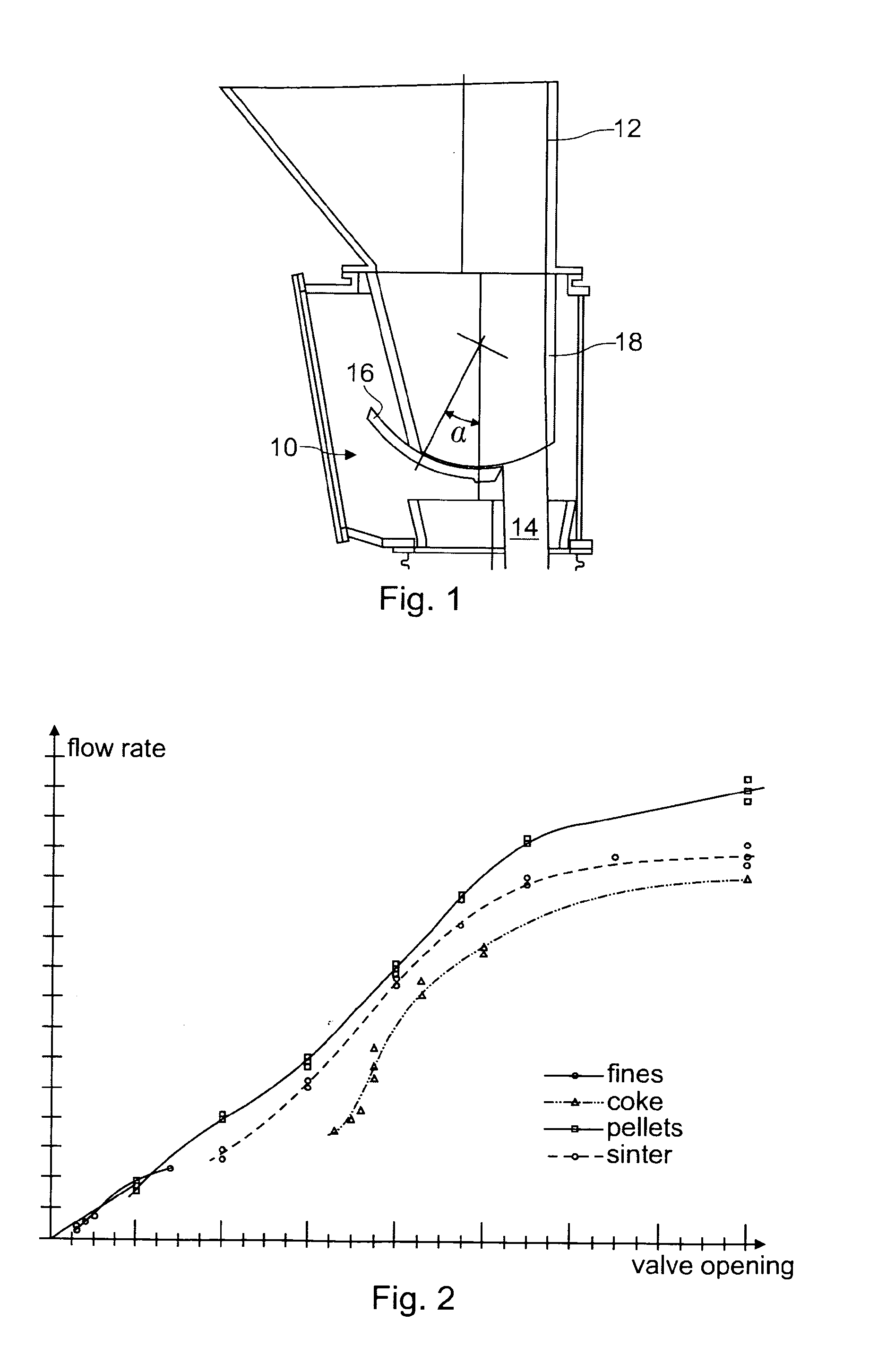
[0026]FIG. 1 schematically illustrates a flow control valve 10 at the outlet of a top hopper 12 in a blast furnace top charging installation, e.g. according to PCT application no. WO 2007 / 082630. During batchwise discharge of charge material, the flow control valve 10 is used to control the (mass or volumetric) flow rate. As is well known, for a proper charging profile, the flow rate has to be coordinated with the operation of a distribution device to which material is fed in form of a flow 14 as illustrated in FIG. 1. Typically, the flow rate is to be coordinated with the operation of a rotating and pivoting distribution chute (not shown). As will be understood, the flow rate is a process variable determined primarily by the valve opening (aperture area / open cross-section) of the valve 10.

[0027]In the embodiment illustrated in FIG. 1, the flow control valve 10 is configured according to the general principles of U.S. Pat. No. 4,074,835, i.e. with a pivotable throttling shutter 16 s...


PUM

PropertyMeasurementUnit
flow rateaaaaaaaaaa
flow rateaaaaaaaaaa
chargeaaaaaaaaaa

Abstract

In a charging process of a shaft furnace, in particular of a blast furnace, batches of charge material are typically discharged in cyclical sequence into the furnace from a top hopper using a flow control valve. A method and system is proposed for adjusting the flow rate of charge material in such a process. Pre-determined valve characteristics for certain types of material are provided, each indicating the relation between flow rate and valve setting for one type of material. According to the invention, a specific valve characteristic is stored for each batch of charge material, each specific valve characteristic being bijectively associated to one batch and indicating the relation between flow rate and valve setting of the flow control valve specifically for the associated batch. In relation to discharging a given batch of the sequence the invention proposes: using the stored specific valve characteristic associated to the given batch for determining a requested valve setting corresponding to a flow rate setpoint and using the requested valve setting to operate the flow control valve; determining an actual average flow rate for the discharge of the given batch; correcting the stored specific valve characteristic associated to the given batch in case of a stipulated deviation between the flow rate setpoint and the actual average flow rate.

Description

TECHNICAL FIELD[0001]The present invention generally relates to the charging process of a shaft furnace, in particular a blast furnace. More specifically, the present invention relates to a method and a system for adjusting the flow rate of charge material from a top hopper into the furnace using a flow control valve.BACKGROUND[0002]It is well known that, besides proper burdening of materials, the geometrical distribution of charge material in a blast furnace has a decisive influence on the hot metal production process since it determines among others the gas distribution. In order to achieve a desired distribution profile in view of an optimal process, two basic aspects are of importance. Firstly, material is to be directed to the appropriate geometric locus on the stock-line for achieving a desired pattern, typically a series of closed concentric rings or a spiral. Secondly, the appropriate amount of charge material per unit surface is to be charged over the pattern.[0003]Regardin...

Claims


Application Information

Patent Timeline
Patent Type & Authority Applications(United States)
IPC IPC(8): F27D3/00
CPCC21B7/20C21B7/24C21B2300/04F27B1/20F27D2003/105F27D19/00F27D21/0035F27D2019/0075F27D2019/0087F27B1/28C21B5/008
Inventor TOCKERT, PAULBREDEN, EMILELONARDI, EMILEMEYER, DAMIEN
Owner PAUL WURTH SA
Why Eureka
Try Eureka