Delivery System and Method for Self-Centering a Proximal End of a Stent Graft

a delivery system and stent technology, applied in the field of endoluminal blood vessel repair, can solve the problems of insufficient, insufficient, and insufficient in endoluminally securing the stent graft, so as to reduce the likelihood of vessel puncture, increase blood-tight vascular connection, and improve the resistance to migration

Inactive Publication Date: 2011-12-22
BOLTON MEDICAL INC
View PDF7 Cites 116 Cited by
  • Summary
  • Abstract
  • Description
  • Claims
  • Application Information

AI Technical Summary

Benefits of technology

[0036]The invention provides a delivery system and method for self-centering a proximal end of a stent graft that overcome the hereinafore-mentioned disadvantages of the heretofore-known devices and methods of this general type and that provides a vessel repair device that implants / conforms more efficiently within the natural or diseased course of the aorta by aligning with the natural curve of the aorta, decreases the likelihood of vessel puncture, increases the blood-tight vascular connection, retains the intraluminal wall of the vessel position, is more resistant to migration, and delivers the stent graft into a curved vessel while minimizing intraluminal forces imparted during delivery and while minimizing the forces needed for a user to deliver the stent graft into a curved vessel.

Problems solved by technology

Because blood flow within the lumen of the graft could be impaired if the framework was disposed on the interior wall of the graft, the framework is connected typically to the exterior wall of the graft.
One of the significant dangers in endovascular graft technology is the possibility of the graft migrating from the desired position in which it is installed.
When the introducer system holding the stent graft positioned in an appropriate location in the vessel and allowed to open, the radial force imparted by the self-expanding framework is helpful, but, sometimes, not entirely sufficient, in endoluminally securing the stent graft within the vessel.
Thus, the rips in the graft body can lead to the possibility of the exposed stent moving with respect to the graft and of the graft body ripping further.
Such points, however, create a very significant possibility of piercing the vessel.
Even though the end-most portion of the stent is curved, because it is relatively narrow, it still creates the possibility of piercing the vessel wall.
All of these prior art stents suffer from the disadvantageous characteristic that the relatively sharp proximal apices of the exposed stents have a shape that is likely to puncture the vessel wall.
Therefore, a device having unsecured stents, could behave like an accordion, or concertina with each systolic pulsation, and may have a tendency to migrate downstream.
Such movement is entirely undesirable.
Thus, the material 8 cannot provide support in the longitudinal extent of the stent graft.

Method used


Image

  • Delivery System and Method for Self-Centering a Proximal End of a Stent Graft
  • Delivery System and Method for Self-Centering a Proximal End of a Stent Graft
  • Delivery System and Method for Self-Centering a Proximal End of a Stent Graft

Examples


Embodiment Construction

[0243]While the specification concludes with claims defining the features of the invention that are regarded as novel, it is believed that the invention will be better understood from a consideration of the following description in conjunction with the drawing figures, in which like reference numerals are carried forward.

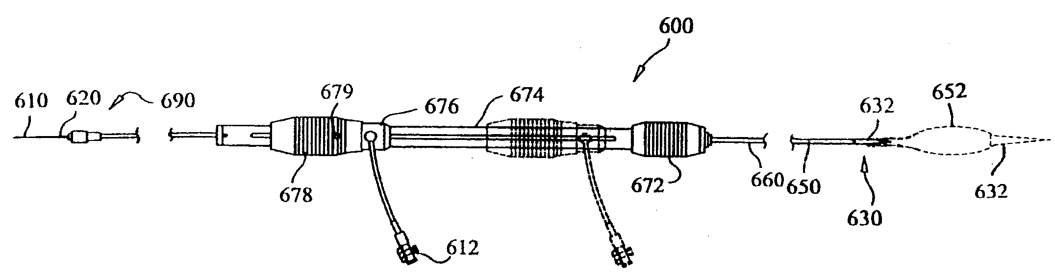
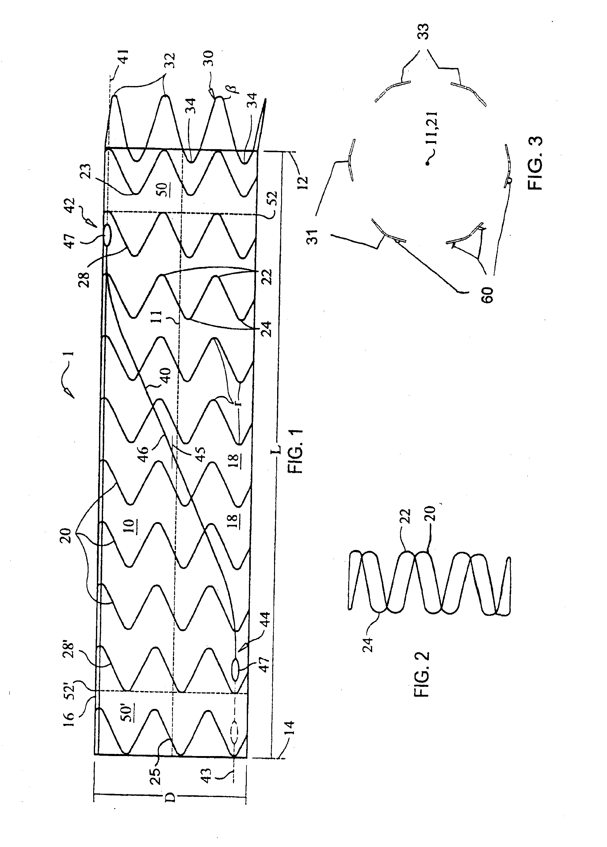
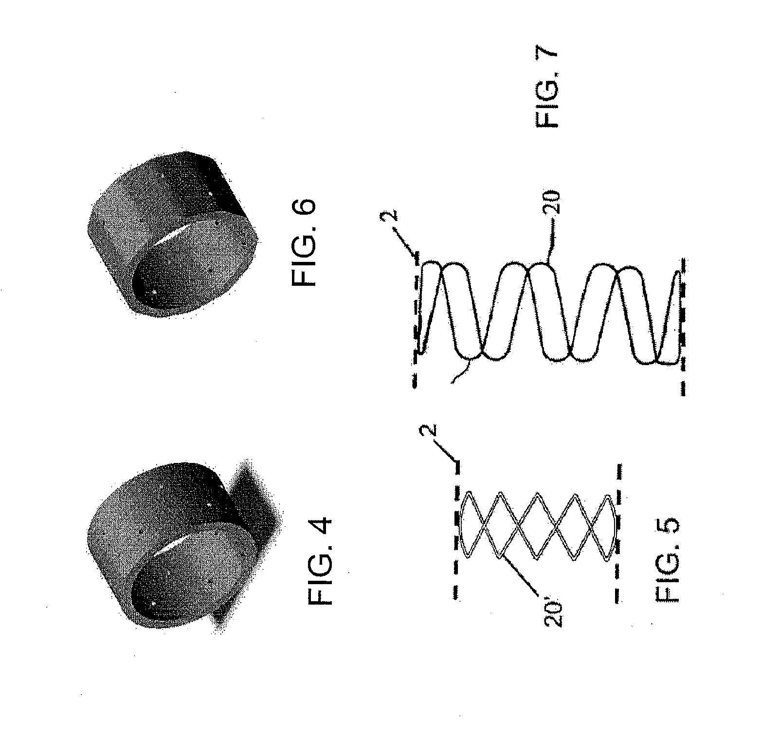
[0244]The present invention provides a stent graft, delivery system, and method for implanting a prosthesis with a two-part expanding delivery system that treats, in particular, thoracic aortic defects from the brachiocephalic level of the aortic arch distally to a level just superior to the celiac axis and provides an endovascular foundation for an anastomosis with the thoracic aorta, while providing an alternative method for partial / total thoracic aortic repair by excluding the vessel defect and making surgical repair of the aorta unnecessary. The stent graft of the present invention, however, is not limited to use in the aorta. It can be endoluminally inserted in...


PUM


Abstract

A method for implanting a prosthesis centrally within a curved lumen includes loading a prosthesis into a delivery sheath, advancing the sheath in a patient towards the curved lumen to place at least the proximal end of the prosthesis within the curved lumen, and centering the proximal end of the prosthesis and / or the distal end of the sheath within the curved lumen. In a first advancing step, the outer catheter containing the inner sheath is advanced together towards the curved lumen to a location proximal of the curved lumen and, in a second advancing step, the inner sheath containing the prosthesis is advanced into the curved lumen to place at least the proximal end within the curved lumen while the outer catheter substantially remains at the location. After centering, the proximal end of the prosthesis is deployed centered within the curved lumen.

Description

CROSS-REFERENCE TO RELATED APPLICATIONS[0001]This application is a continuation of U.S. patent application Ser. No. 11 / 701,876, filed Feb. 1, 2007, which claims the benefit under 35 U.S.C. §119(e) of U.S. Provisional Applications Nos. 60 / 851,282, filed Oct. 12, 2006, 60 / 833,533, filed Jul. 26, 2006, and 60 / 765,449, filed Feb. 3, 2006. U.S. application Ser. No. 11 / 701,876 is also a continuation-in-part of U.S. patent application Ser. Nos. 10 / 884,136, filed Jul. 2, 2004, which claims the benefit under 35 U.S.C. §119(e) of U.S. Provisional Applications Nos. 60 / 500,155, filed Sep. 4, 2003, and 60 / 499,652, filed Sep. 3, 2003; and is also a continuation-in-part of Ser. No. 10 / 784,462, filed Feb. 23, 2004, which also claims the benefit under 35 U.S.C. §119(e) of U.S. Provisional Applications Nos. 60 / 500,155, filed Sep. 4, 2003, and 60 / 499,652, filed Sep. 3, 2003. The entire teachings of the above applications are incorporated herein by reference.STATEMENT REGARDING FEDERALLY SPONSORED RESE...

Claims


Application Information

Patent Timeline
Patent Type & Authority Applications(United States)
IPC IPC(8): A61F2/84A61F2/06
CPCA61F2/07A61F2/95A61F2002/9505A61F2002/9511A61F2002/9517A61F2/848A61F2230/008A61F2002/825A61F2002/91525A61F2002/9665A61F2250/0048A61F2/89A61F2002/075A61F2/9517A61F2/966A61F2/9526A61F2/04A61F2/06A61F2/82A61F2/9522
Inventor BERRA, HUMBERTOARBEFEUILLE, SAMUELCHRISTIAN, FLETCHERLOSTETTER, TIMOTHYBORREGO, FRANKOUELLETTE, GERRYMOORE, MICHAEL
Owner BOLTON MEDICAL INC
Why Eureka
Try Eureka