Method of manufacturing "t" shaped stringers for an aircraft and curing tool used thereof

a technology of composite stringers and stringers, which is applied in the field of aircraft stringers and “ t”-shaped composite stringers, can solve the problems of increasing assembly difficulties, increasing stringer thickness, and increasing the amount of work involved

Active Publication Date: 2011-12-29
AIRBUS OPERATIONS SL
View PDF6 Cites 16 Cited by
  • Summary
  • Abstract
  • Description
  • Claims
  • Application Information

AI Technical Summary

Benefits of technology

[0036]A further advantage of the present invention relates to the weight of the invar alloy angles, as with the proposed solution the weight of the invar alloy angles is lower than the weight of traditional invar alloy angles with their conventional geometry.
relates to the weight of the invar alloy angles, as with the proposed solution the weight of the invar alloy angles is lower than the weight of traditional invar alloy angles with their conventional geometry.

Problems solved by technology

These “T” shaped stringers, being formed under the traditional manufacturing methods in which uncured stringers are co-bonded on cured skins with the stringer curing tool inside the vacuum bag, are subjected to “Mexican hat effect” drawback which is the fact that the stringer thickness becomes:smaller than the nominal thickness at the end of the stringer web, andgreater than the nominal thickness at the ends of the stringer feet.
The use of these solid shims increases assembly difficulties and the amount of work involved.

Method used


Image

  • Method of manufacturing "t" shaped stringers for an aircraft and curing tool used thereof
  • Method of manufacturing "t" shaped stringers for an aircraft and curing tool used thereof
  • Method of manufacturing "t" shaped stringers for an aircraft and curing tool used thereof

Examples


second embodiment

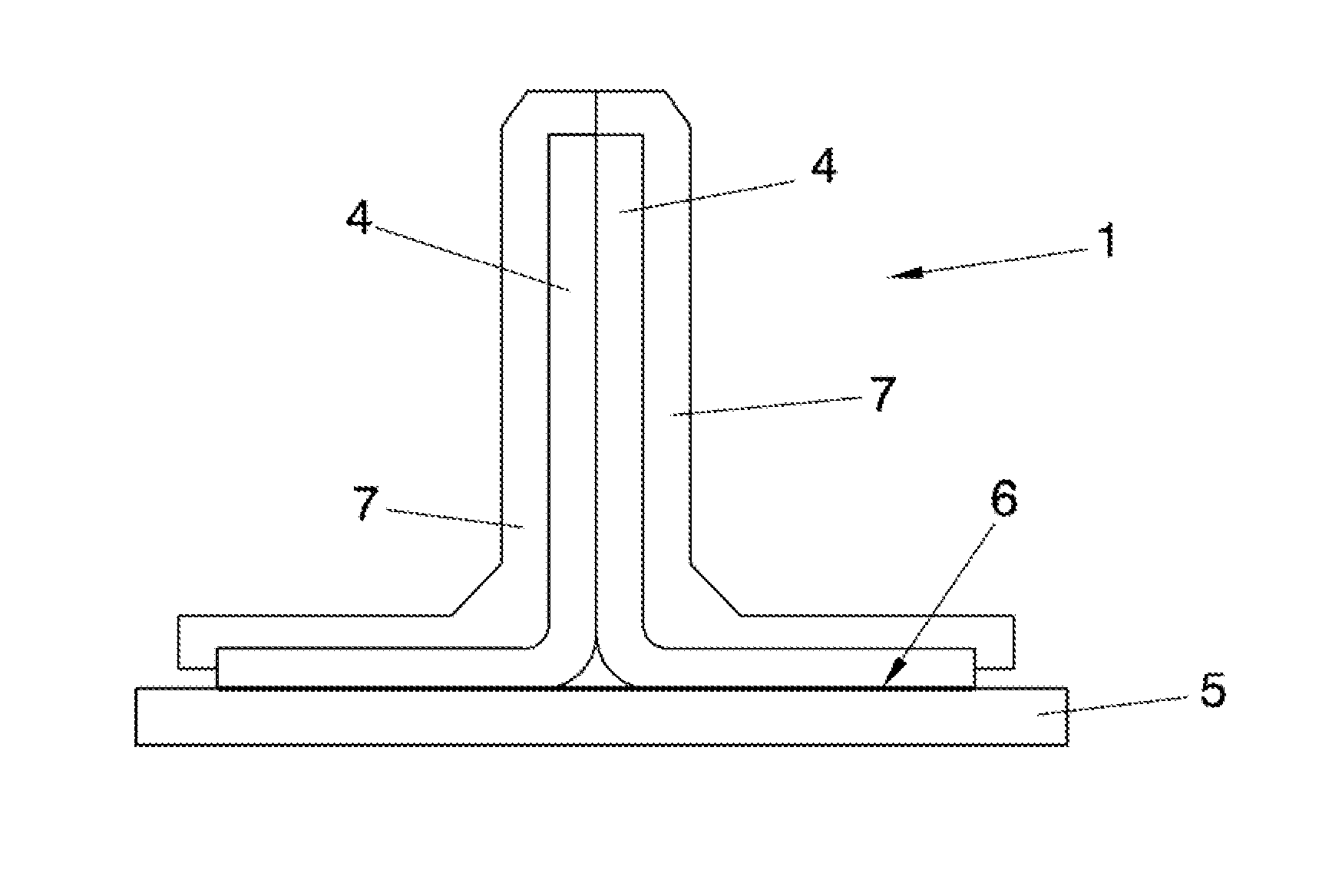
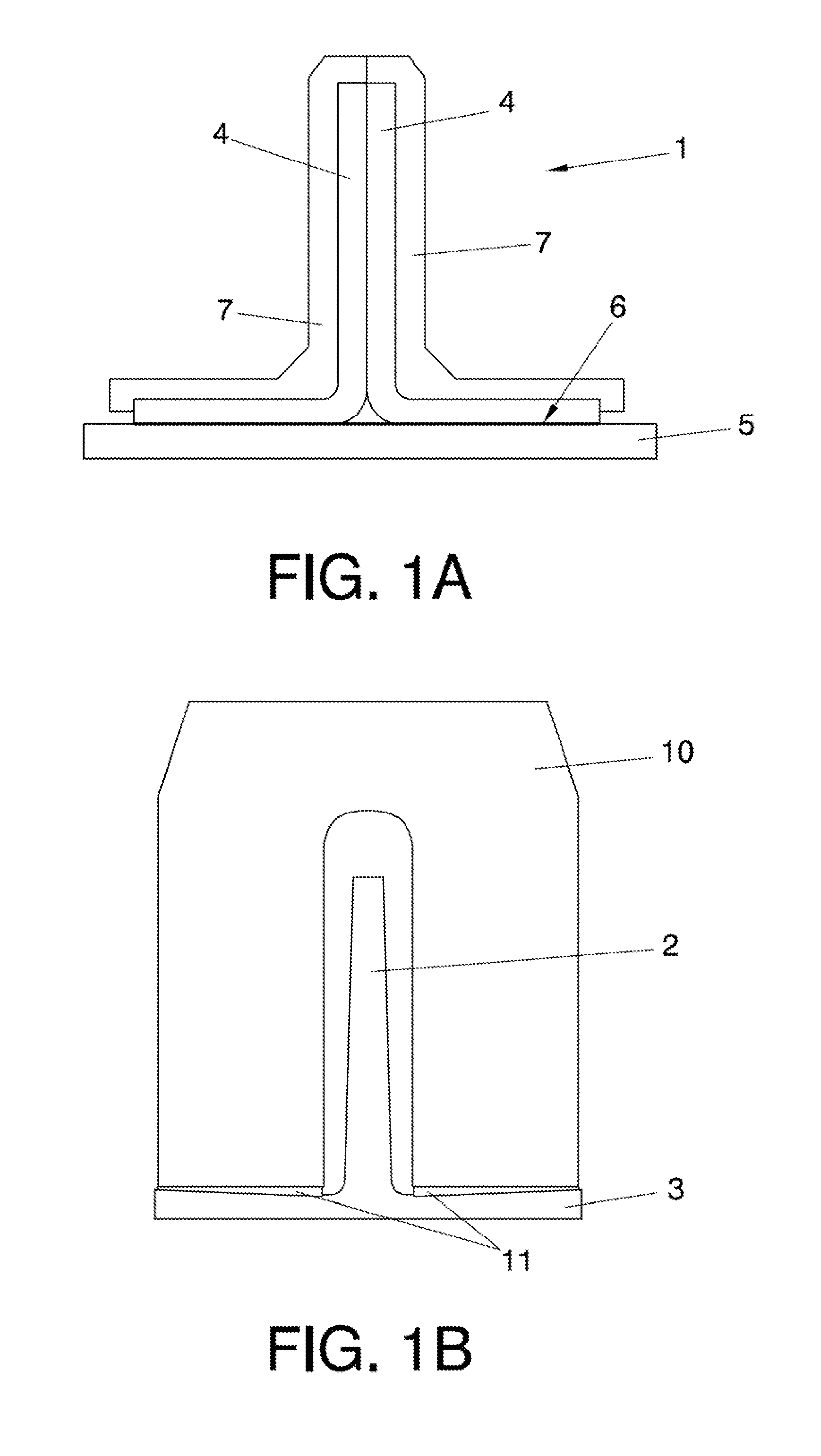
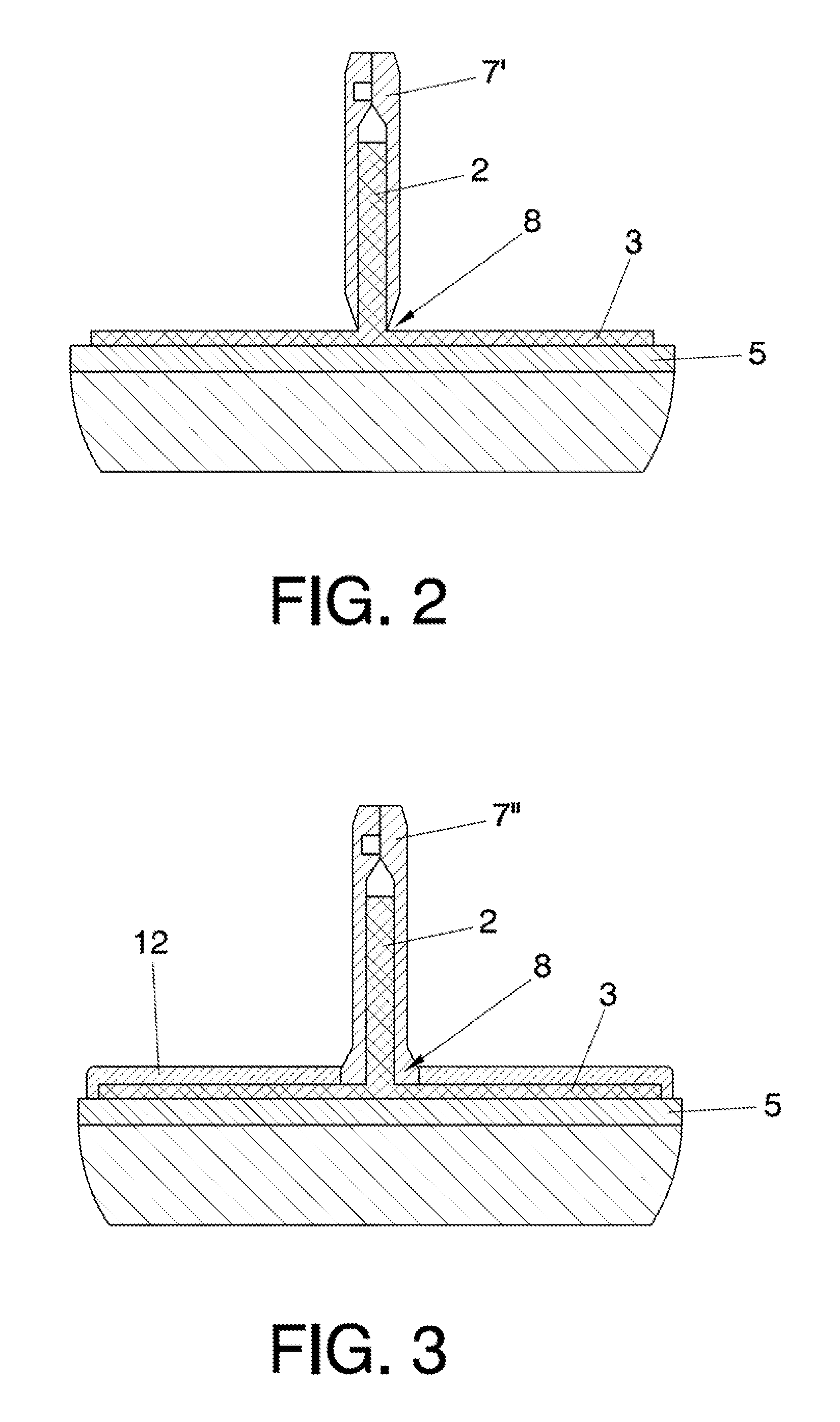
[0027]On the present invention, an elastomeric pad is arranged on the stringer foot once the invar alloy angles have been cut. The elastomeric pad covers the stringer foot.

third embodiment

[0028]In addition, in order to enhance demoulding of the stringers the present invention co-bonds cured glass fiber on the stringer foot in the place left by the part of the invar alloy angle eliminated, this cured glass fiber is in direct contact with the release film of the vacuum bag during the curing cycle.

[0029]The cured glass fiber can be placed:[0030]before hot-forming the stringers, or[0031]once the stringers are hot-formed, but before placing the invar angles.

[0032]Furthermore, when more than one “T” shaped stringers are co-bonded at the same time on a cured skin, the present invention uses a filler, placed between adjacent stringers foot, in order to avoid the edge effect. The edge effect is produced because the material, before being cured and during the curing cycle is a rather soft, thus the vacuum bag tends to make round the corners which are not protected by the invar piece.

[0033]The filler is selected from the group consisting of carbon fiber, metal, glass fiber or a...


PUM

PropertyMeasurementUnit
anglesaaaaaaaaaa
invar anglesaaaaaaaaaa
invar angleaaaaaaaaaa

Abstract

Method of manufacturing “T” shaped stringers for an aircraft whereby the “T” shaped stringers have a stringer web and a stringer foot, the method comprising: a first step of hot-forming a carbon fiber laminate in order to achieve semi-stringers geometry with an “L” shaped cross-section, a second step of placing together two hot-formed “L” shaped semi-stringers in order to form a “T” shaped stringer, a third step of co-bonding the resulting “T” shaped stringer on a cured skin with an adhesive line between them, and a fourth step of curing the obtained “T” shaped stringer inside a vacuum bag using invar alloy angles as curing tools. The method characterised in that the invar alloy angles are cut at a radius area eliminating a part of the invar alloy angles covering the stringer foot in order to define an invar alloy piece having no foot.

Description

OBJECT OF THE INVENTION[0001]It is an object of the present invention to provide a method of manufacturing “T” shaped stringers for building structures of aircrafts that reduces assembly time, work and difficulties, especially when another piece is assembled on the stringers.[0002]The main object of the present invention is to minimize an effect known as the “Mexican hat effect” undergone by “T” shaped stringers. This means to minimize the fact that the stringer thickness becomes smaller than the nominal thickness at the end of the stringer web and greater than the nominal thickness at the end of the stringer foot.[0003]Thus, it is a further object of the invention to avoid the use of solid shims when another piece is to be assembled on the stringer foot.[0004]A further object of the present invention is to describe a curing tool used for overcoming above-mentioned effect.[0005]Lastly, another object of the present invention relates to facilitating the step of demoulding of the stri...

Claims


Application Information

Patent Timeline
Patent Type & Authority Applications(United States)
IPC IPC(8): B32B37/02B32B37/14B32B37/12
CPCB29C70/446B29C70/543B29K2105/0872B29L2031/3082B29L2031/001B29L2031/30B29K2307/04B29D99/0014Y10T156/1002Y10T156/1028Y02T50/40B29C37/0053
Inventor PEREZ PASTOR, AUGUSTOSANCHEZ FERNANDEZ, JULIANESQUIVIAS GARC A, FERNANDO
Owner AIRBUS OPERATIONS SL
Why Eureka
Try Eureka