Direct forced draft fluid cooler/cooling tower and liquid collector therefor

a technology of liquid collector and cooler, which is applied in the direction of machines/engines, lighting and heating apparatus, heating types, etc., can solve the problems of large basins or sumps, high maintenance costs, and workers, and achieves the effect of reducing the initial construction cost of modular units, reducing the overall height of the structure, and easy access to fan units

Inactive Publication Date: 2011-12-29
CURTIS HAROLD +1
View PDF3 Cites 23 Cited by
  • Summary
  • Abstract
  • Description
  • Claims
  • Application Information

AI Technical Summary

Benefits of technology

[0027]As will be appreciated from the above discussion, the direct forced draft counterflow systems of the present invention provide many advantages as compared to induced draft counterflow water cooling towers which are now most commonly used in the industry.
[0028]First, there is a major advantage in reduced initial construction costs of the modular units due to the elimination of the water basin, the louver and the overall height of the structure. They also can be prefabricated, whereas the typical site built induced draft counterflow cooling towers can not.
[0029]Second, accessibility to the fan units is very easy since the space below the fans is open allowing them to be accessed from below.
[0030]Third, the fan units of the present invention cause a very turbulent impacting on the air which flows upward in the water collector and through the fill material or heat transfer coils thus causing a better distribution of the air and better cooling as the air turbulently impacts water flowing down through the tower. This is contrasted in induced draft cooling towers where the air flow is in a rather laminar fashion.
[0031]Another advantage is that fan efficiency in general is greatly improved when using a fan in a forced draft mode rather than in a induced draft mode. Further, having the fan very close to the fill material or heat transfer coils reduces functional flow pressure losses of the air again improving fan efficiency.
[0032]In summary, the water collection system, when utilized in water operated equipment, offers many cost saving features as well as eliminating health and safety risk associated with water equipment including:

Problems solved by technology

These basins or sumps are typically very large because they have to contain enough liquid to charge the system, including all associated piping.
Such basins are maintenance intense and require workers to enter and work in a confined space to perform cleaning.
At the same time the large volume of liquid itself may require water or chemical treatment rather than disposal, further adding to costs.
Moreover, the volume of liquid in such systems greatly increases the weight of the system and thus increases rooftop loading.
In addition to the issues of sedimentation, liquid volume and disposal, previously proposed tower systems have not adequately addressed the problem of air diffusion by their respective liquid collection systems.
The fans in such systems are, of course, round and the air is not evenly distributed across the tower media or elements since the fans do not deliver a balanced air flow.
These factors significantly affect the quality and dispersion of the air entering the tower and thus reduces thermal performance of the tower.

Method used


Image

  • Direct forced draft fluid cooler/cooling tower and liquid collector therefor
  • Direct forced draft fluid cooler/cooling tower and liquid collector therefor
  • Direct forced draft fluid cooler/cooling tower and liquid collector therefor

Examples


Embodiment Construction

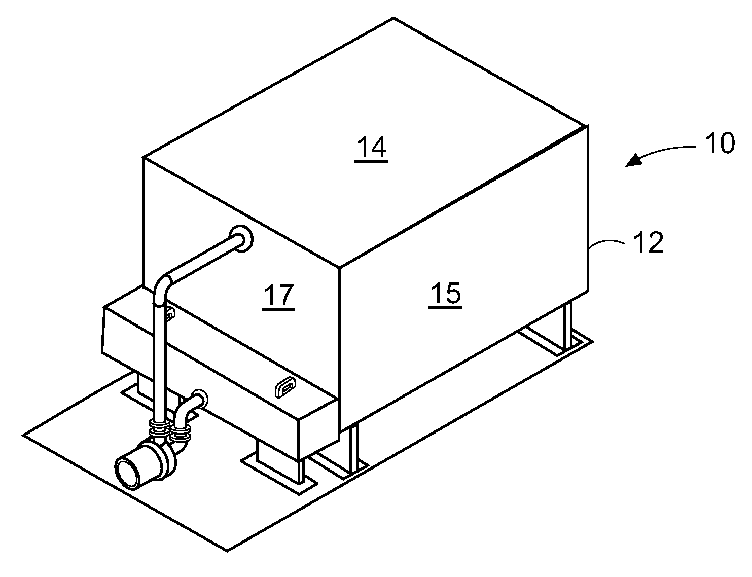
[0072]Referring now to the drawings in detail, and initially to FIG. 1, a direct draft fluid cooler 10 is illustrated. The cooler is designed to advantageously use the evaporation of water or other liquids to cool a second liquid in a heat exchanger located within the device. The systems of the invention can be used with water or other suitable liquids and although the illustrative embodiments are described as utilizing water the invention is not so limited.

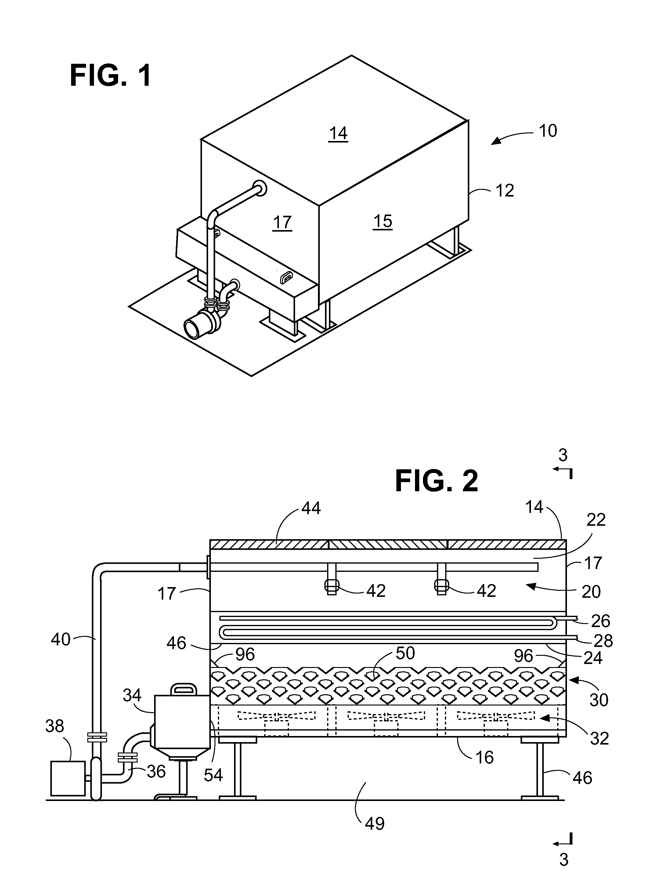
[0073]Fluid cooler 10 includes an exterior housing 12 having an open top 14, vertical side walls 15, end walls 17 and a bottom wall 16. As seen in FIG. 2, wherein the side wall 15 has been removed to illustrate the interior of the cooler, housing 12 contains a liquid distribution system 20 at its upper end 22, and a heat exchanger 24 illustrated in the drawing as a cooling coil type structure. The latter is formed as curved piping having an inlet end 26 for supplying liquid to be cooled to the heat exchanger and an outlet end 28 ...


PUM


Abstract

Direct forced draft fluid cooler/closed loop cooling towers and cooling towers are provided with fans at the bottom of the unit, and a plurality of layers of water collection troughs or channels above the fans to capture water droplets sprayed downwardly from the top of the device through a heat exchanger or fill media above the collection troughs. In one embodiment the collection troughs supply the collected water to one or more gutters inside the housing which lead the water to an external collection tank from which the water is recirculated through the system.

Description

[0001]This application claims the benefit U.S. Provisional Application Nos. 61 / 208,995 filed Mar. 3, 2009; 61 / 217,822, filed Jun. 5, 2009; and 61 / 270,723 filed Jul. 13, 2009, the disclosures of which are incorporated herein by reference.BACKGROUND OF THE INVENTION[0002]The present invention relates generally to direct forced draft fluid coolers / closed loop cooling towers and / or compact cooling towers and more particularly to an improved air diffusing water drainage collection system for such coolers and towers.DESCRIPTION OF THE PRIOR ART[0003]Conventional types of industrial cooling towers include so-called counterflow towers wherein water or other liquid falls or is sprayed downward in the tower counter flow to air moving upwardly in the tower, in the opposite direction. Such systems are used for a variety of applications including water air scrubbers, dust collection equipment, air cooling towers, evaporative coolers, fluid coolers or closed loop cooling towers, evaporative conde...

Claims


Application Information

Patent Timeline
Patent Type & Authority Applications(United States)
IPC IPC(8): F28D15/02
CPCF28D5/02F28F25/04F28C1/00F28F25/02Y10T137/8593F24F3/12F28C1/02
Inventor CURTIS, HAROLD DEAN
Owner CURTIS HAROLD
Why Eureka
Try Eureka