Cutting Elements for Cutting Tools

Active Publication Date: 2011-12-29
BAKER HUGHES INC
View PDF5 Cites 19 Cited by
  • Summary
  • Abstract
  • Description
  • Claims
  • Application Information

AI Technical Summary

Benefits of technology

In one particular embodiment, the cutting elements are disposed on blades of a downhole cutting tools that are disposed on a face of the tool. The blades are disposed on the face such that rotation of the tool causes rotation of the blades. One or more of the blades include a front side surface that has disposed on it one or more cutting elements, and a back side surface. The back side surface generally does not include any cutting elements. The presence of the cutting element on the blade allows the blade to cut objects during rotation. In addition, the presence of the cutting element along a beveled portion of the blade allows the positioning of the cutting elements such that the center point of the face of the downhole cutting tool is covered by a cutting element. In this arrangement, rotation of the downhole cutting tool provides for the portion of

Problems solved by technology

To facilitate these operations, cutting elements are disposed on the downhole cutting tool; however, the shape, size, and design of the cutting elements can limit the locations in which the cutting elements can be placed.
For example, the shape, size,

Method used


Image

  • Cutting Elements for Cutting Tools
  • Cutting Elements for Cutting Tools
  • Cutting Elements for Cutting Tools

Examples


Example

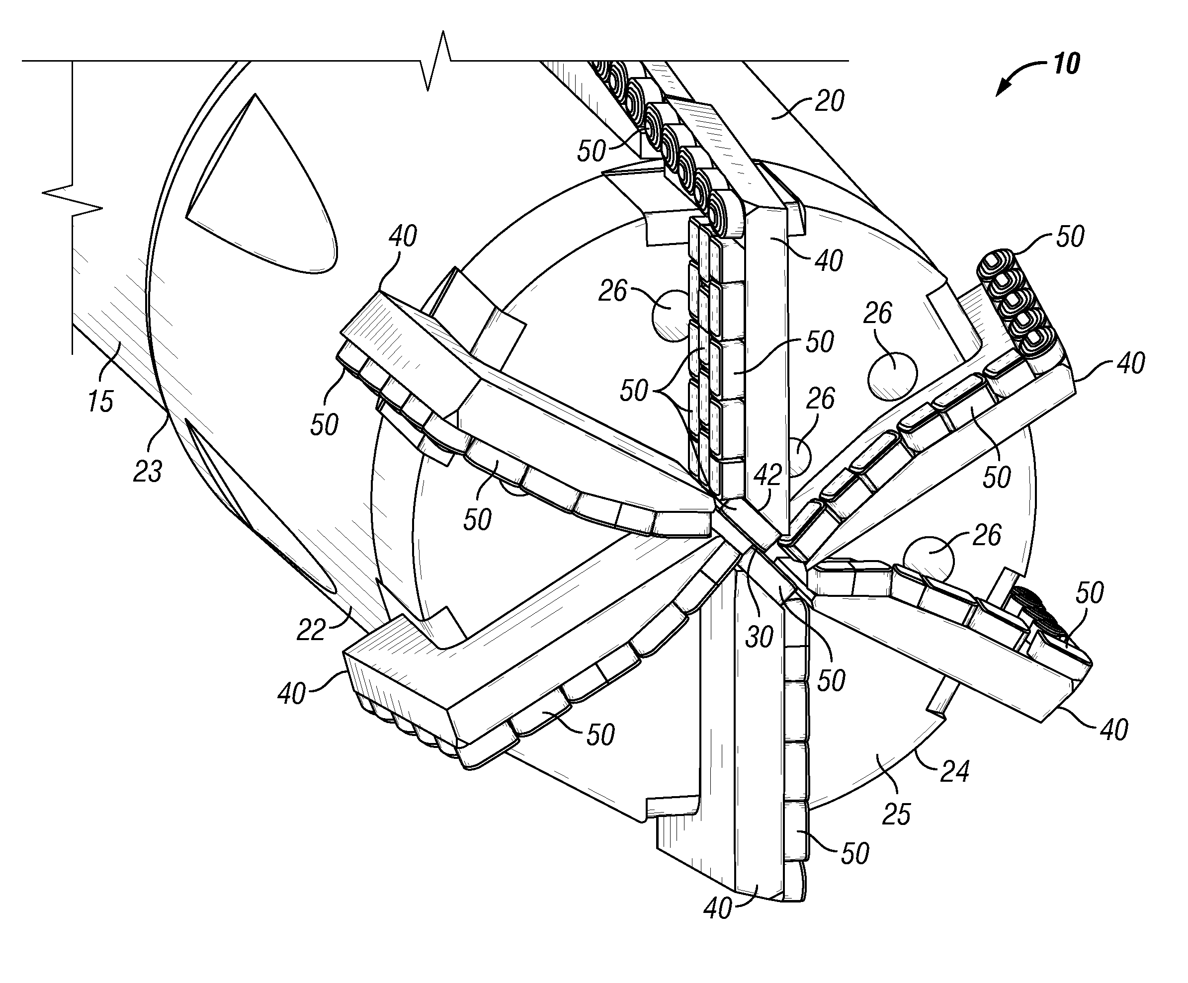
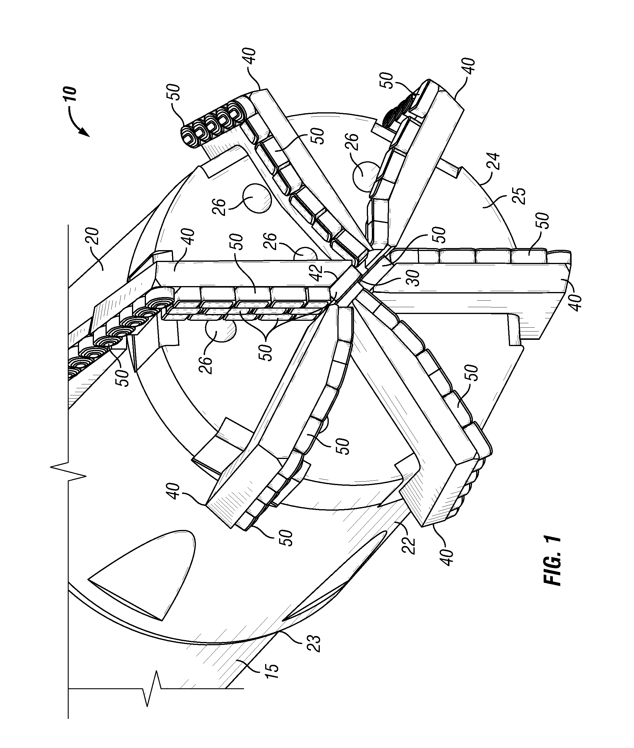
Referring now to FIG. 1, downhole cutting tool 10 comprises blade mill 20 having body or housing 22 adapted at upper end 23 to be connected to drill or work string 15, cutting end 24 having face 25, drilling fluid ports 26 through which drilling or cutting fluid flows to facilitate cutting by blade mill 20, and, as shown in the specific embodiment in the Figures, six blades40. Affixed to a front or forward face of each of the six blades 40 are one or more cutting elements 50. In addition, as shown in FIG. 1, two cutting elements 50 are disposed on beveled portions 42 of blades 40 facing toward each other across center point 30 of face 25 so that the portion of the object below center point 30 can be cut by cutting elements 50. And, as further shown in FIG. 1, these two cutting elements 50 disposed on beveled portions 42 overlap one another to facilitate cutting the portion of the object below the center point This overlapping increases the strength and durability of these two cuttin...


PUM

PropertyMeasurementUnit
Fractionaaaaaaaaaa
Angleaaaaaaaaaa
Angleaaaaaaaaaa

Abstract

Cutting elements for downhole cutting tools comprise a top surface having a cutting surface portion and a cutting profile disposed across the top surface. The cutting elements comprise first and second longitudinal side surfaces and first and second lateral side surfaces, each having a respective cross-section. The cutting profile can be disposed on the cutting surface either asymmetrically or symmetrically. Asymmetrical disposition permits two cutting elements to be arranged facing each other to cover a center point of a cutting tool. The cutting edge of asymmetrical or symmetrically disposed cutting profiles can have a shape that facilitates self-sharpening during cutting.

Description

BACKGROUND1. Field of InventionThe invention is directed to cutting elements or “cutters” for cutting tools and, in particular, to cutting elements that comprise a cutting profile disposed across a top surface of the cutting element wherein the cutting profile self-sharpens during cutting of objects, including objects such as stuck tools, bridge plugs, well tubing, well casing, and the like disposed within an oil or gas well and / or wherein the cutting elements can be disposed on a cutting tool so that the portion of the object disposed below the center point of the cutting tool can be cut.2. Description of ArtIn the drilling, completion, and workover of oil and gas wells, it is common to perform work downhole in the wellbore with a tool that has some sort of cutting profile interfacing with a downhole structure. Examples would be milling a downhole metal object with a milling tool or cutting through a tubular with a cutting or milling tool. To facilitate these operations, cutting el...

Claims


Application Information

Patent Timeline
IPC IPC(8): E21B7/00B24B1/00E21B10/00
CPCB24D99/005E21B29/002E21B10/54E21B10/006E21B10/43E21B10/55E21B10/62
Inventor STOWE II, CALVIN J.PONDER, ANDREW D.
Owner BAKER HUGHES INC
Why Eureka
Try Eureka