Methods and Apparatus for Adaptive Operation of Solar Power Systems

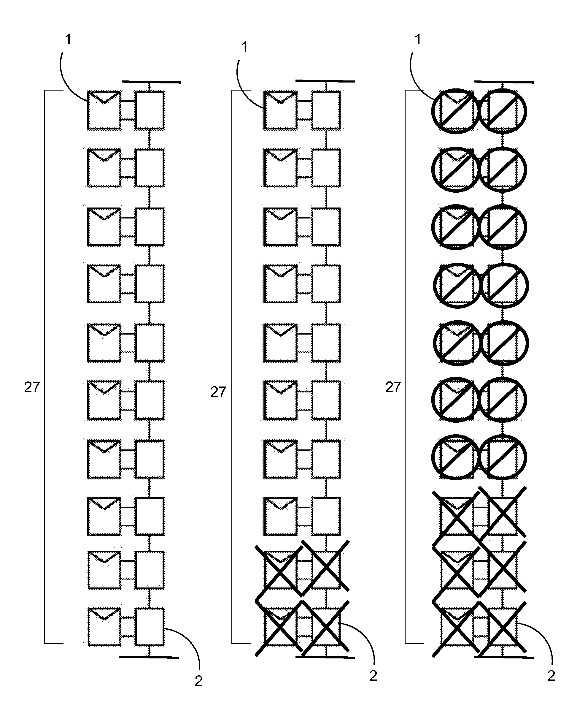
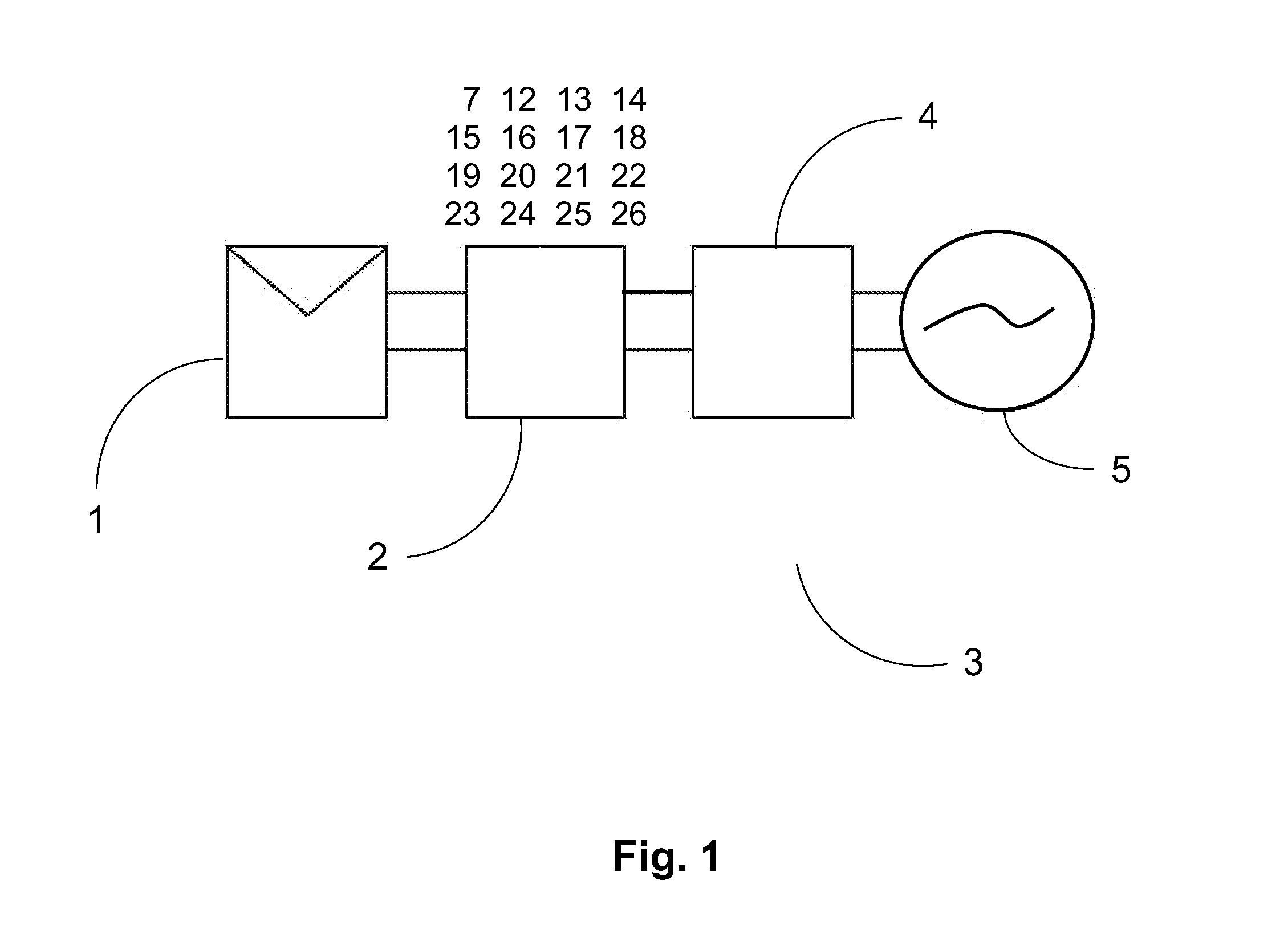
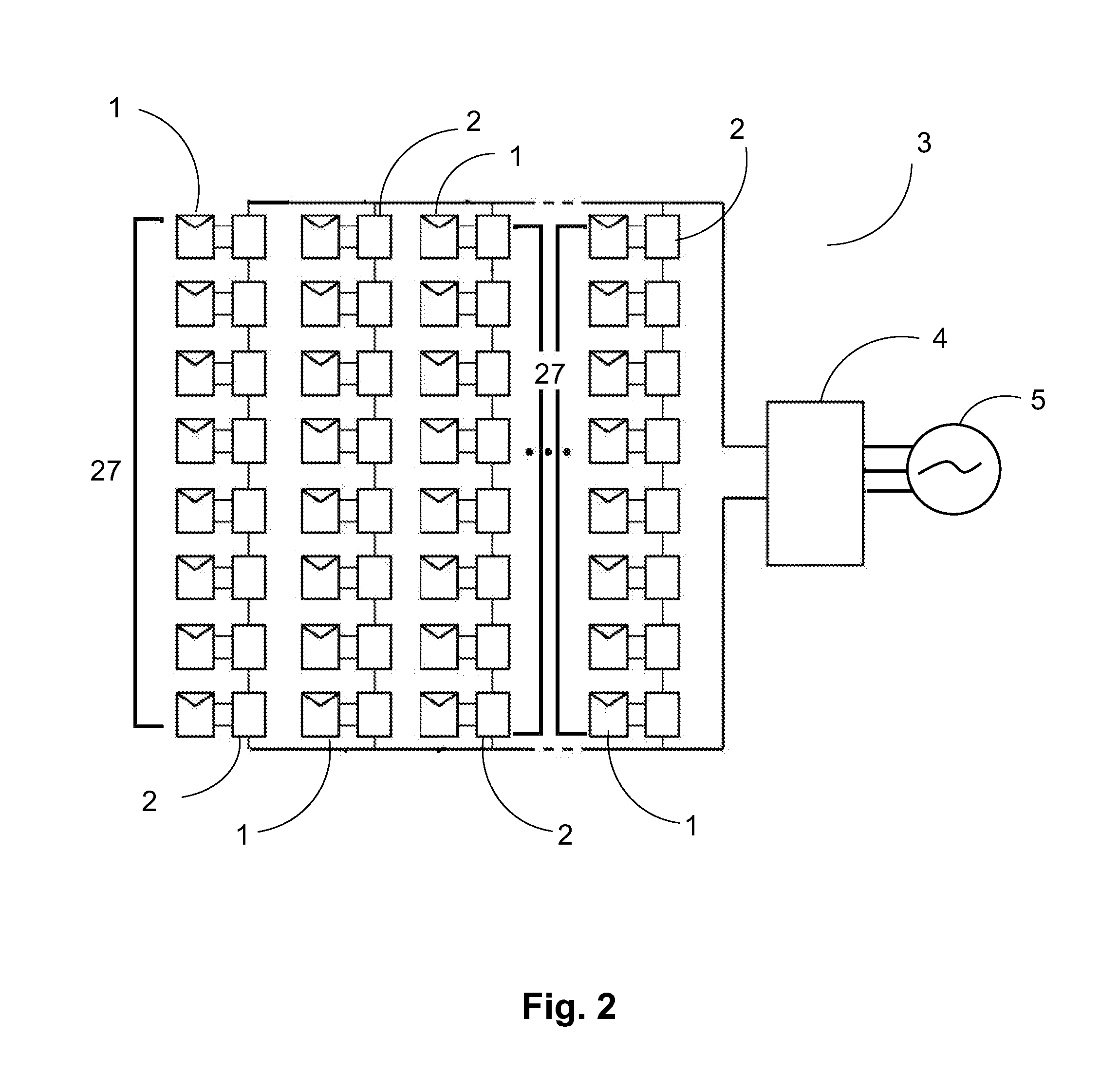
a solar power system and solar energy technology, applied in the direction of electrical equipment, electric variable regulation, instruments, etc., can solve the problems of loss of power for the array of strings connected in parallel, significant challenges remain in the field of exploiting this technology, and inconsistent and efficient operating voltage of the solar power system may pose technical challenges

Active Publication Date: 2011-12-29
AMPT
View PDF3 Cites 184 Cited by
  • Summary
  • Abstract
  • Description
  • Claims
  • Application Information

AI Technical Summary

Benefits of technology

[0009]The inventive technology relates to methods and apparatus for adaptive operation of solar power systems and in embodiments may include the following the features: techniques for providing one or more external state parameters to a photovoltaic DC-DC power converter; techniques for relationally setting a dynamically adjustable voltage output limit for a photovoltaic DC-DC powe

Problems solved by technology

While solar power is a promising source of renewable energy, significant challenges remain with respect to exploiting this technology.
One such challenge may involve a susceptibility of solar power systems to be influenced by a wide range of operating conditions.
Because a typical solar power system may have a large number of individual solar sources, each operating essentially within its own conditional framework, the task of combining the voltage outputs of these various solar sources to achieve a consistent and efficient operating voltage of the solar power system may pose technical challenges.
If the voltage in the string drops below a certain level, this may cause a loss of power for the array of strings connected in parallel, due to their parallel interconnection.
At another extreme, spikes in the output of individual solar sources in a string may cause a voltage gain for the string as whole, which again may result in inefficiencies due to the connection topology.
Such spikes in voltage may be undesirable for efficiency, safety, or regulatory reasons.
For example, solar power sy

Method used


Image

  • Methods and Apparatus for Adaptive Operation of Solar Power Systems
  • Methods and Apparatus for Adaptive Operation of Solar Power Systems
  • Methods and Apparatus for Adaptive Operation of Solar Power Systems

Examples


Embodiment Construction

[0019]As mentioned earlier, the present inventive technology includes a variety of aspects, which may be combined in different ways. The following descriptions are provided to list elements and describe some of the embodiments of the present inventive technology. These elements are listed with initial embodiments, however it should be understood that they may be combined in any manner and in any number to create additional embodiments. The variously described examples and preferred embodiments should not be construed to limit the present inventive technology to only the explicitly described systems, techniques, and applications. Further, this description should be understood to support and encompass descriptions and claims of all the various embodiments, systems, techniques, methods, devices, and applications with any number of the disclosed elements, with each element alone, and also with any and all various permutations and combinations of all elements in this or any subsequent ap...


PUM


Abstract

Methods and apparatus may provide for the adaptive operation of a solar power system (3). Solar energy sources (1) and photovoltaic DC-DC power converters (2) may be interconnected in serial, parallel, or combined arrangements. DC photo-voltaic power conversion may be accomplished utilizing dynamically adjustable voltage output limits (8) of photovoltaic DC-DC power converters (2). A photovoltaic DC-DC power converter (2) may include at least one external state data interface (7) receptive to at least one external state parameter of a solar power system (3). A dynamically adjustable voltage output limit control (12) may be used to relationally set a dynamically adjustable voltage output limit (8) of a photovoltaic DC-DC power converter (2). Dynamically adjusting voltage output limits (8) may be done in relation to external state parameter information to achieve desired system results.

Description

TECHNICAL FIELD[0001]Generally, the inventive technology relates to adaptively operating a solar power system. More particularly, the inventive technology may involve dynamically adjusting voltage output limits within the system to achieve desired operating voltages. The inventive technology may be particularly suited to adapting system operation to changing conditions or unforeseen events.BACKGROUND[0002]While solar power is a promising source of renewable energy, significant challenges remain with respect to exploiting this technology. One such challenge may involve a susceptibility of solar power systems to be influenced by a wide range of operating conditions. This susceptibility in part may stem from the architecture by which solar power systems typically are designed. In particular, solar power systems generally may utilize a distributed architecture, wherein a relatively large number of individual solar sources—such as solar panels—are used to generate power from sunlight. Wh...

Claims


Application Information

Patent Timeline
IPC IPC(8): H02J1/00
CPCY02E10/58G05F1/67Y02E10/56H02J3/38
Inventor PORTER, ROBERT M.LEDENEV, ANATOLI
Owner AMPT
Why Eureka
Try Eureka