Image processing apparatus and image processing method

a technology of image processing and image processing, applied in the field of image processing apparatus and image processing method, to achieve the effect of suppressing density fluctuations

Active Publication Date: 2011-12-29
CANON KK
View PDF7 Cites 12 Cited by
  • Summary
  • Abstract
  • Description
  • Claims
  • Application Information

AI Technical Summary

Benefits of technology

[0016]According to the present invention, it is possible to suppress density fluctuations caused by registration misalignment in an overlapped portion of a connected head.

Problems solved by technology

However, this patent document does not clearly specify a method for suppressing density fluctuations in an overlapped portion of the connected heads.
However this patent document does not describe a method for suppressing density fluctuations in an overlapped portion in such a connected head.

Method used


Image

  • Image processing apparatus and image processing method
  • Image processing apparatus and image processing method
  • Image processing apparatus and image processing method

Examples


first embodiment

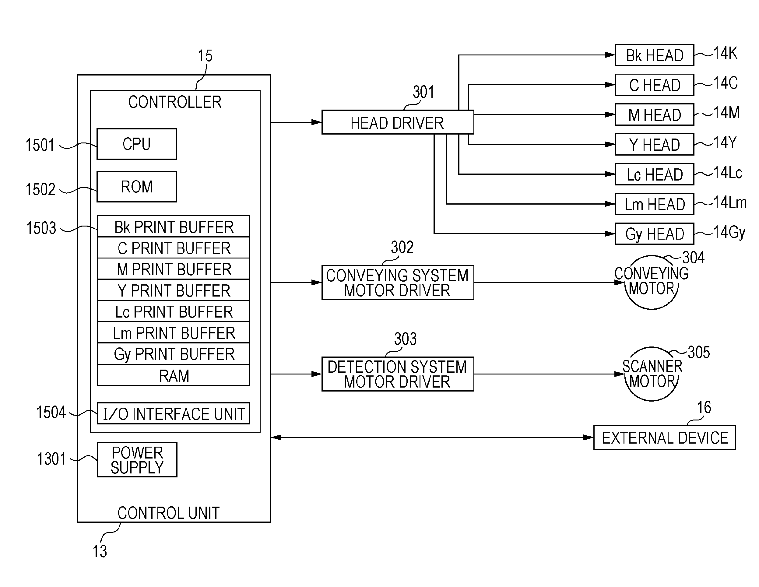
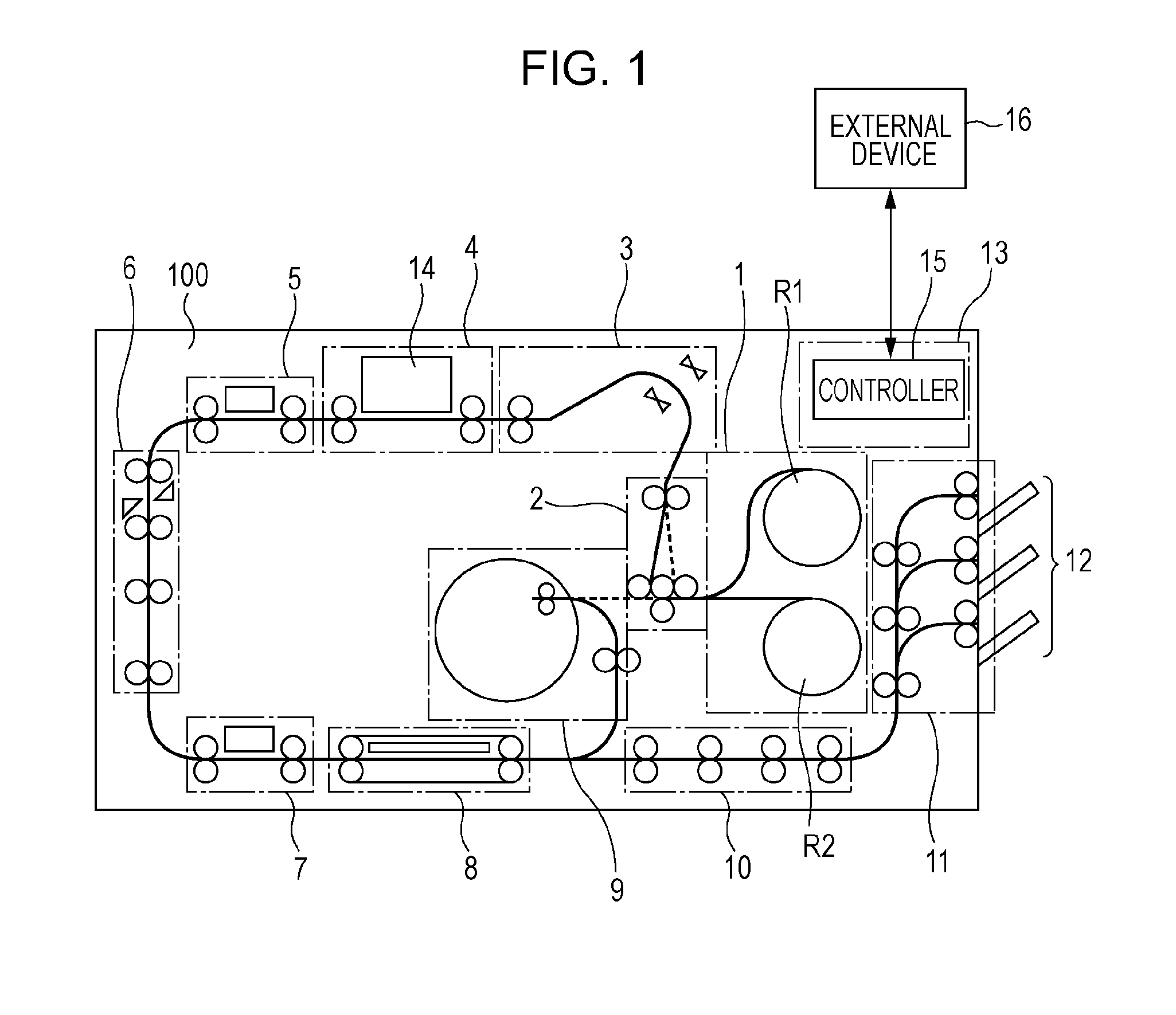
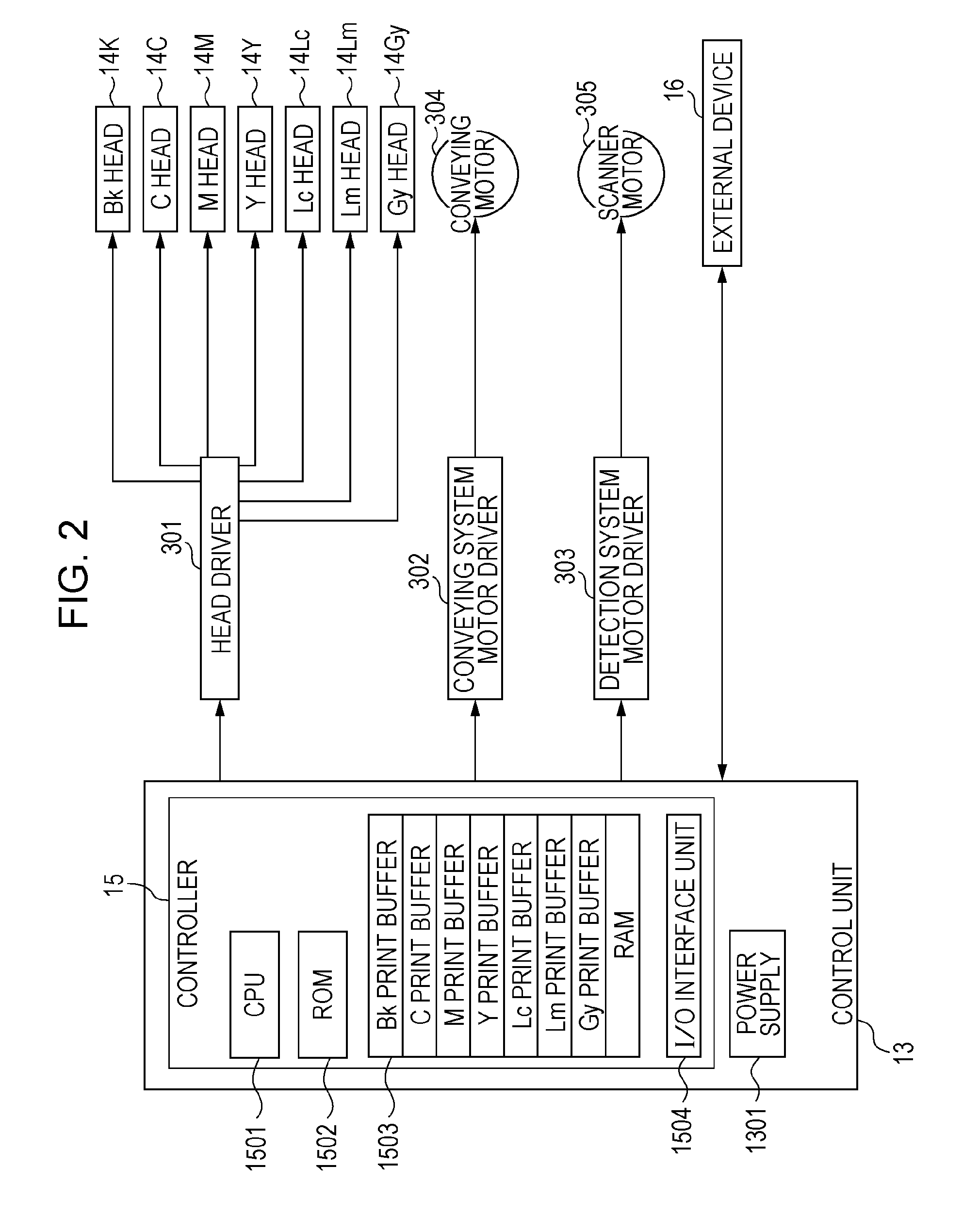
[0049]FIG. 1 is a schematic diagram of an inkjet recording apparatus (hereinafter, also simply referred to as a recording apparatus or a printer) to which the present invention can be applied. A printer 100 shown in FIG. 1 is an inkjet recording apparatus for relatively moving a recording head that ejects ink with respect to a recording medium and performing recording. The printer 100 includes a sheet supply unit 1, a de-curl unit 2, a skew correction unit 3, a printing unit 4, an inspection unit 5, a cutter unit 6, an information recording unit 7, a drying unit 8, a sheet winding unit 9, a discharge conveying unit 10, a sorter 11, a discharge tray 12, and a control unit 13. The recording medium (sheet) is conveyed by a conveying mechanism including a roller pairs and a belt along a sheet conveying path shown by solid lines in FIG. 1 and processed by each unit.

[0050]The sheet supply unit 1 is a unit for containing and supplying rolled-up continuous sheets. The sheet supply unit 1 ca...

second embodiment

[0103]Next, a second embodiment of the present invention will be described. The same reference symbols are given to the same constituent elements as those described in the first embodiment, and the description thereof will be omitted.

[0104]FIG. 27 is a diagram for explaining an outline of a connected head according to this embodiment. In FIG. 27, in the connected head, a plurality of chips including the first chip 31 and the second chip 32 are arranged in a zigzag pattern in a direction crossing the conveying direction. In each chip, a plurality of nozzle arrays are arranged in a direction perpendicular to the conveying direction. Each chip includes a plurality of nozzle arrays, and a part of nozzles of the first chip and the second chip are arranged to be overlapped with each other. In this example, the nozzle interval is 1200 dpi, the number of nozzle arrays in each chip is 8, and the number of nozzles in the overlapped portion is 128. The nozzle arrays are referred to as A to H i...


PUM


Abstract

When distributing image data of a plurality of planes to a first chip and a second chip that constitute the same overlapped portion of a connected head, a distribution method is changed for at least a part of the plurality of planes.

Description

BACKGROUND OF THE INVENTION[0001]1. Field of the Invention[0002]The present invention relates to an image processing apparatus and an image processing method for processing multivalued image data in an area corresponding to an overlapped portion of nozzle arrays in order to record an image by using a recording head in which a plurality of nozzle arrays are arranged so that the overlapped portion is included in a direction crossing a direction in which the nozzle arrays are arranged.[0003]2. Description of the Related Art[0004]Conventionally, a recording apparatus is known which uses a recording head (a connected head) in which chips including a nozzle array in which a plurality of nozzles are arranged are arranged in a zigzag pattern. It is known that, as a recording apparatus that uses the connected head, there is a recording apparatus using serial method for performing recording by causing a recording head to scan in a direction crossing the arrangement direction of recording elem...

Claims


Application Information

Patent Timeline
Patent Type & Authority Applications(United States)
IPC IPC(8): B41J29/38
CPCB41J2/2146B41J29/38B41J29/393G06K15/107H04N1/1934G06K2215/111H04N1/12H04N1/1903G06K15/1898
Inventor AZUMA, SATOSHIMURAYAMA, YOSHIAKIKOSAKA, KEI
Owner CANON KK
Why Eureka
Try Eureka