Image Pickup System

a pickup system and image technology, applied in the field of image pickup systems, can solve the problems of difficult structure, difficult to have an effect of distortion of the taking lens, etc., and achieve the effect of not correcting distortion, increasing the distortion of the photographic optical system, and improving the parameters of image quality

Inactive Publication Date: 2011-12-29
OLYMPUS CORP
View PDF6 Cites 36 Cited by
  • Summary
  • Abstract
  • Description
  • Claims
  • Application Information

AI Technical Summary

Benefits of technology

[0013]Moreover, in an image pickup apparatus disclosed in Japanese Patent Application Laid-open Publication No. 2008-40087, disposing a plurality of photoelectric conversion portions to make it possible to receive separately each light beam having a pupil divided as a structure of a pixel for ranging, has been proposed. According to this structure, by adding outputs from the plurality of photoelectric conversion portions formed in one pixel for ranging at the time of image formation, it is possible to reduce practically a difference of aperture efficiency with the pixel for image formation. On the other hand, since it is same as increasing the number of pixels of the image pickup element practically, the structure becomes difficult.
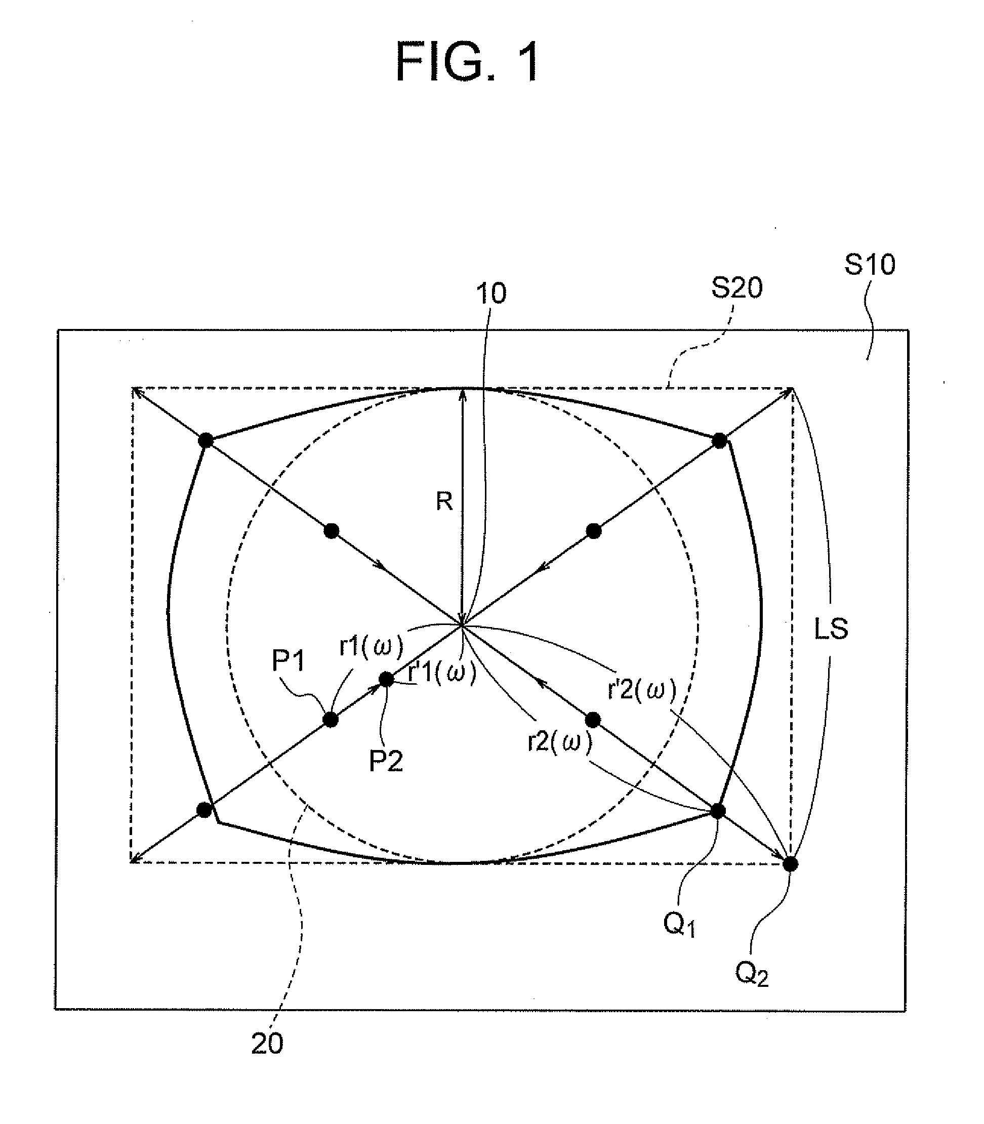
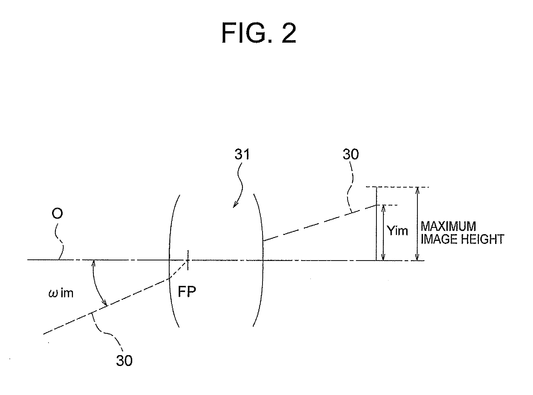
[0014]Incidentally, in the conventional single-lens reflex camera, since two images which are to be compared in a focus detecting optical system are formed from the same position of a primary image formation surface, it has been hard to have an effect of distortion of the taking lens. Moreover, since an optical finder which observes directly an image which is formed by the taking lens, even for eliminating an uncomfortable feeling due to direct observation, excluding a special lens such as a fish-eye lens, the distortion of the taking lens has been corrected quite favorably optically.
[0016]Moreover, in the so-called compact digital camera, as disclosed in Japanese Patent Application Laid-open Publication No. 2004-264343, improving parameters of image quality other than distortion, and small-sizing of a photographic optical system have been proposed instead of increasing the distortion of the photographic optical system. In this case, it is common to use the contrast AF, and a phase-difference AF system in which, a light beam which has passed through the taking lens, has not been applied.

Problems solved by technology

On the other hand, since it is same as increasing the number of pixels of the image pickup element practically, the structure becomes difficult.
Incidentally, in the conventional single-lens reflex camera, since two images which are to be compared in a focus detecting optical system are formed from the same position of a primary image formation surface, it has been hard to have an effect of distortion of the taking lens.

Method used


Image

  • Image Pickup System
  • Image Pickup System
  • Image Pickup System

Examples


second modified embodiment

[0133]FIG. 8 is a plan view showing conceptually a pixel arrangement in an imager according to a first modified embodiment of the embodiment of the present invention. FIG. 9 is a plan view showing conceptually a pixel arrangement in an imager according to the embodiment of the present invention.

first modified embodiment

[0134]In the first modified embodiment, a direction of dividing a pupil, is let to be an upper side and a lower side in addition to a right side and a left side. In FIG. 8, an example of 16 vertical pixels (L01 to L16) and 16 horizontal pixels (F01 to F16), in all 256 pixels has been shown. However, the number of pixels is not restricted to 256, and it may be an arrangement in which, the total number of pixels is more than 10 million for example.

[0135]In the example shown in FIG. 8, the directions in which, the center of area of the photoelectric conversion cell is shifted with respect to the pixel center are four types namely, the right side, the left side, the upper side, and the lower side. In the following description, the pixels will be called as a right pixel 131, a left pixel 132, an upper pixel 133, and a lower pixel 134.

[0136]In FIG. 8, in row L01, the right pixel 131, the left pixel 132, the lower pixel 134, and the lower pixel 134 are disposed repeatedly in order from lef...

third modified embodiment

[0141]FIG. 10 is a cross-sectional view showing a schematic structure of pixels according to the embodiment of the present invention. FIG. 11 is a diagram when the pixels shown in FIG. 10 are seen from a direction of optical axes 200L and 200R.

[0142]In FIG. 10 and FIG. 11, adjacent pixels are shown, and an area of photoelectric conversion areas 205L and 205R is same. However, a distance between positions of centers of gravity of area of the photoelectric conversion areas 205L and 205R and a distance of pixel pitch differ, which is similar as in the example shown in FIG. 3 and FIG. 4.

[0143]In FIG. 10 and FIG. 11, micro lenses 201L and 201R are disposed to correspond with pixels 204L and 204R respectively of a sensor. A distance between the micro lenses 201L and 201R is according to the pixel pitch. However, taking into consideration an output pupil position of a taking lens, the micro lenses 201L and 201R may be disposed at a distance shorter than the pixel pitch from a center toward...


PUM


Abstract

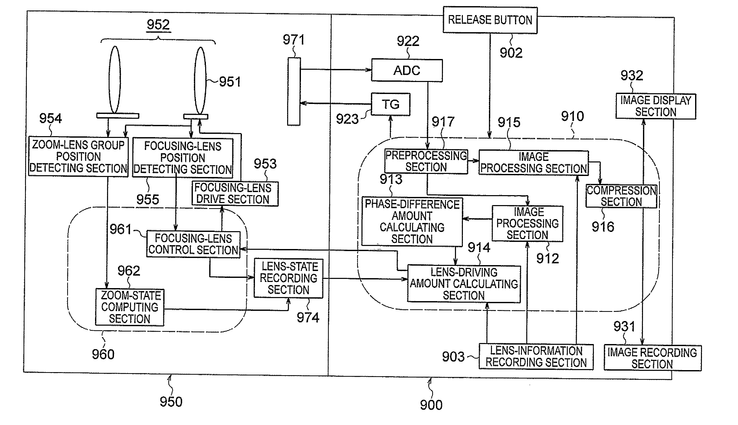
An image pickup system includes an image pickup apparatus in which, photoelectric conversion cells are arranged two-dimensionally, and at least some of the photoelectric conversion cells are arranged to output a signal for detecting an amount of defocus. The photoelectric conversion cells which output the signal for detecting the amount defocus form at least two photoelectric conversion cell groups, each receiving a light beam from a pupil area having different area. Each photoelectric conversion cell group has a plurality of photoelectric conversion cell columns. The image pickup system includes a calculating section which has an AF mode which generates a defocus signal by comparing mutually the signals for detecting the amount of defocus which have been output from the two photoelectric conversion cell groups, and a correction section which corrects the signal for detecting the amount of defocus, from information related to distortion of the taking lens.

Description

CROSS-REFERENCE TO RELATED APPLICATION[0001]The present application is based upon and claims the benefit of priority from the prior Japanese Patent Application No. 2010-145818 filed on Jun. 28, 2010; the entire contents of which are incorporated herein by reference.BACKGROUND OF THE INVENTION[0002]1. Field of the Invention[0003]The present invention relates to an image pickup system.[0004]2. Description of the Related Art[0005]In a conventional digital still camera, an AF (auto focus) type such as the following has been realized.[0006]In other words, a sensor for AF has been provided separately apart from an image pickup element. A typical example is a phase-difference AF which is used in a single-lens reflex camera. A merit of this type is that a problem of parallax is solved by using a light beam which has passed through a taking lens, and it is possible to detect a focal shift by a one-time defocus amount detection signal, and to focus the taking lens to an object, and it is poss...

Claims


Application Information

Patent Timeline
Patent Type & Authority Applications(United States)
IPC IPC(8): H04N5/217
CPCG02B7/346G03B3/10H04N5/3696H04N5/23212H04N5/3572G03B13/36H01L27/14627H01L27/14623H04N23/672H04N23/673H04N25/61H04N25/704H04N25/134
Inventor GOTO, HISASHI
Owner OLYMPUS CORP
Why Eureka
Try Eureka