Image processing apparatus and image forming apparatus

Active Publication Date: 2011-12-29
SHARP KK
View PDF1 Cites 2 Cited by
  • Summary
  • Abstract
  • Description
  • Claims
  • Application Information

AI Technical Summary

Benefits of technology

As described earlier, the image processing apparatus in accordance with the present invention includes the density correction adjustment section receiving an instruction to adjust the density correction process carried out by the density correction process section and reviewing the conversion parameter used by the density correction process section, so as to adjust the density correction process.
Therefore, the present invention yields an effect of making an image processing apparatus which carries out a density correction process with higher accuracy even by use of conversion as compared with a conventional arrangement in which a density correction process is carried out by use of a conversion parameter (a conversion value or a conversion expression) which cannot be rewritten and is fixed.

Problems solved by technology

Even an image forming apparatus providing approximately 64-level gray scale often fails to appropriately express gradation in a low-density part and a high-density part of a printed image.
Therefore, this causes problems of (i) costs for materials to be consumed (e.g., toner and ink) and (ii) longer time required for the density correction.

Method used


Image

  • Image processing apparatus and image forming apparatus
  • Image processing apparatus and image forming apparatus
  • Image processing apparatus and image forming apparatus

Examples


first embodiment

A first embodiment of the present invention is described below with reference to FIGS. 1 through 7. The present embodiment discusses an application of an image processing apparatus in accordance with the present invention to an image forming apparatus.

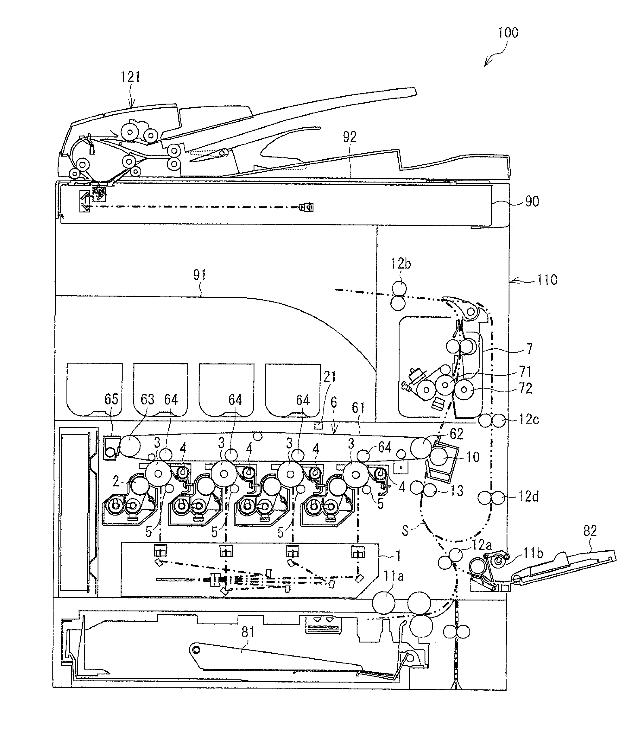
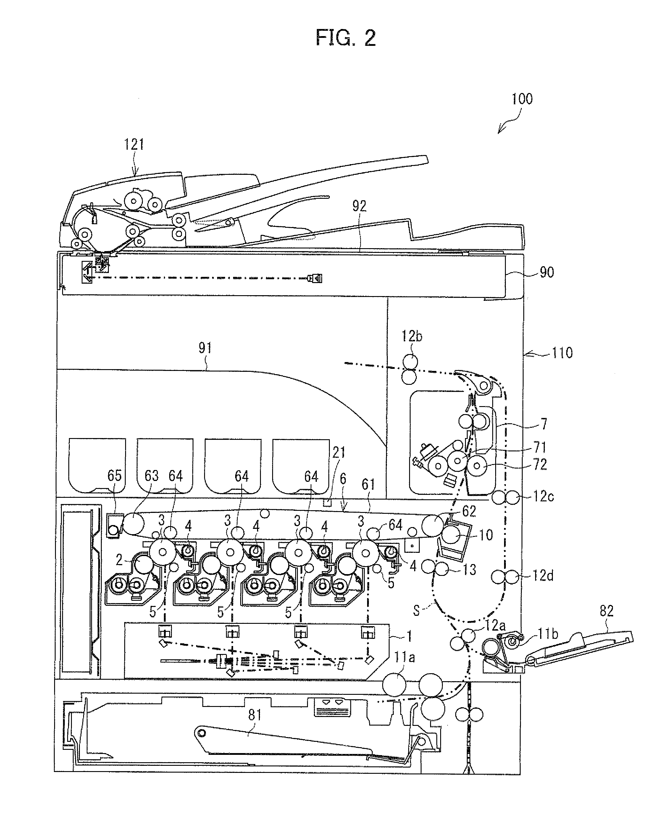
FIG. 2 is a cross-sectional view illustrating an example of an arrangement of an image forming apparatus 100 including an image processing section 20 in accordance with the present invention. In accordance with image data read by the image forming apparatus 100 or received from outside, the image forming apparatus 100 forms a multicolor or single color image on a given recording sheet which is a recording material.

The image forming apparatus 100 includes an apparatus body 110 and an automatically document processing device 121 (see FIG. 2).

The apparatus body 110 mainly includes an exposure unit 1, developing units 2, photoreceptor drums 3, cleaner units 4, chargers 5, an intermediate transfer belt unit 6, a fixing unit 7, a paper feedi...

second embodiment

A second embodiment of the present invention is described below with reference to FIGS. 8 and 9. The present embodiment is to discuss an image forming apparatus which carries out a plurality of halftone processes, the image forming apparatus being arranged such that the number of reference halftone processes is not set to one and the image forming apparatus includes an image processing section which can change the reference halftone processes according to need.

Note that for convenience, members having functions identical to those of the respective members illustrated in the drawings of the First Embodiment are given respective identical reference numerals, and a description of those members is omitted here.

The First Embodiment discussed a case where in the image forming apparatus 100 which carries out a plurality of halftone processes, a density correction is carried out by setting one of the plurality of halftone processes as a reference halftone process and appropriately rewriting...


PUM


Abstract

An image processing section includes a density correction adjustment section, and in response to an instruction from a density correction process section to adjust a density correction process, the density correction adjustment section reviews a conversion value table which is used by the density correction process section to calculate an output correction value by conversion, so as to adjust the density correction process.

Description

This Nonprovisional application claims priority under 35 U.S.C. §119(a) on Patent Application No. 2010-146314 filed in Japan on Jun. 28, 2010, the entire contents of which are hereby incorporated by reference.TECHNICAL FIELDThe present invention relates to an image processing apparatus for carrying out a density correction with respect to an image forming apparatus. More specifically, the present invention relates to (i) an image processing apparatus which has a function of carrying out a plurality of halftone processes, carries out a density correction by actual measurement with respect to only one of the plurality of halftone processes that is required to be subjected to the density correction, and carries out the density correction with respect to the other halftone processes by conversion from a result of the density correction by actual measurement carried out with respect to the only one halftone process and (ii) an image forming apparatus including the image processing appara...

Claims


Application Information

Patent Timeline
IPC IPC(8): H04N1/405
CPCG03G15/011H04N1/6036H04N1/6033H04N1/4078
Inventor YASUOKA, NORIHIDEOTSUKA, MASAYUKIFUJITANI, MASAYANAGAYAMA, KATSUHIROKITAGAWA, TAKASHI
Owner SHARP KK
Why Eureka
Try Eureka