Anchor device for anchoring an element such as a fluid coupling in an opening in a wall

a technology of fluid coupling and anchor device, which is applied in the direction of coupling device connection, shaft, rod connection, etc., can solve the problems of not always possible, requires some time, and the mode of anchoring is relatively heavy and impractical

Inactive Publication Date: 2011-12-29
PARKER HANNIFIN FRANCE
View PDF13 Cites 14 Cited by
  • Summary
  • Abstract
  • Description
  • Claims
  • Application Information

AI Technical Summary

Benefits of technology

[0007]Thus, the attachment member is formed merely of a frustoconical washer received in a groove in the sleeve. The attachment member and the sleeve can then be manufactured independently from each other without giving rise to high manufacturing costs, the shape of the attachment member and the shape of the sleeve remaining relatively simple. The bearing against the zone of intersection between the side surface of the opening and the second surface makes it possible to increase the pull-out resistance of the anchoring by directing the force exerted against the ring by the zone of intersection towards a side of the groove. In addition, the ring makes it possible to take up clearance and to accommodate variations in the thickness of the wall. This bearing, associated with the resilience of the ring, also makes it possible to limit the assembly clearance between the sleeve and the wall.
[0009]Preferably, the ring has an end of smaller section that has a face extending in a substantially radial plane when the ring is in its attachment position so as to bear against a side of the groove that is further from the shoulder. The face of the smaller section of the ring makes it possible to distribute the force transmitted by the ring to the adjacent side of the groove and thereby limits the zones of stress concentration.
[0010]Advantageously, the ring has an inside surface and has an end of smaller section in the vicinity of which the inside surface has a portion that is substantially cylindrical when the ring is in its attachment position. The cylindrical portion enables the ring to be centered properly on the sleeve.
[0011]Advantageously, a plane groove is provided in the shoulder and receives a seal that projects relative to the shoulder, the seal being arranged to be axially compressible. Axial compression of the seal takes place in accordance with the invention while the device is being put in place through the wall (in particular a partition wall). The sloping surface of the frustoconical ring that makes it possible to keep the seal axially deformed, and that thus guarantees that the wall is leaktight in the zone of its opening. It should be noted that, in order for the sloping surface of the frustoconical ring to apply its force correctly for attracting the shoulder of the sleeve, it is preferable for the ring to be concentric with the opening in the wall, and therefore to be concentric with the coupling, which is centered. As described in more detail below, it a guide surface of the ring makes it possible for this coaxial positioning to be achieved.
[0012]It is thus the way the frustoconical ring of the invention is arranged that makes it possible to guarantee that the opening in the wall is sealed in leak-tight manner. The seal can then be used for taking up the assembly clearance, allowed for assembling the sleeve to the wall, by exerting a force on the sleeve that tends to press the larger-section of the ring against the zone of intersection between the second face and the side surface of the opening.

Problems solved by technology

Such mode of anchoring is relatively heavy and impractical, and requires some time.
In addition, such screw-fastening presupposes that access is available to both sides of the wall, which is not always possible, e.g. when the wall defines a tank.
In addition, if the wall and / or the device are subjected to vibration, there exists a risk of the nut working loose, thereby adversely affecting the strength of the fastening.
It is then relatively complicated and costly to make the sleeve.

Method used


Image

  • Anchor device for anchoring an element such as a fluid coupling in an opening in a wall
  • Anchor device for anchoring an element such as a fluid coupling in an opening in a wall
  • Anchor device for anchoring an element such as a fluid coupling in an opening in a wall

Examples


Embodiment Construction

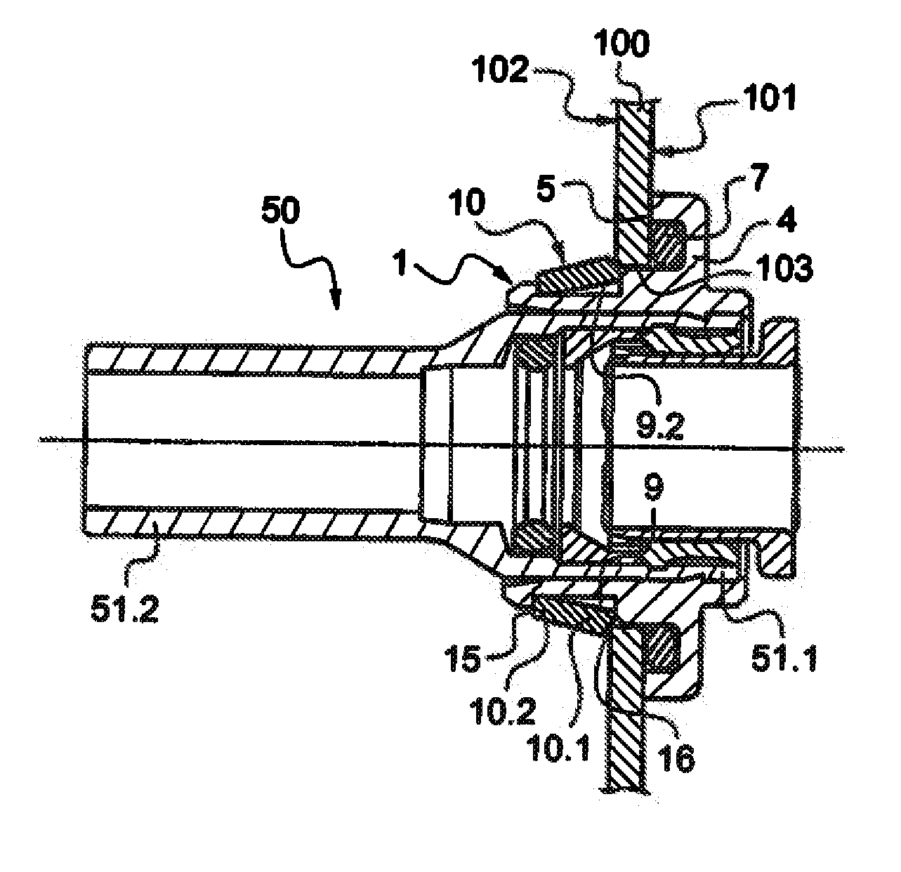
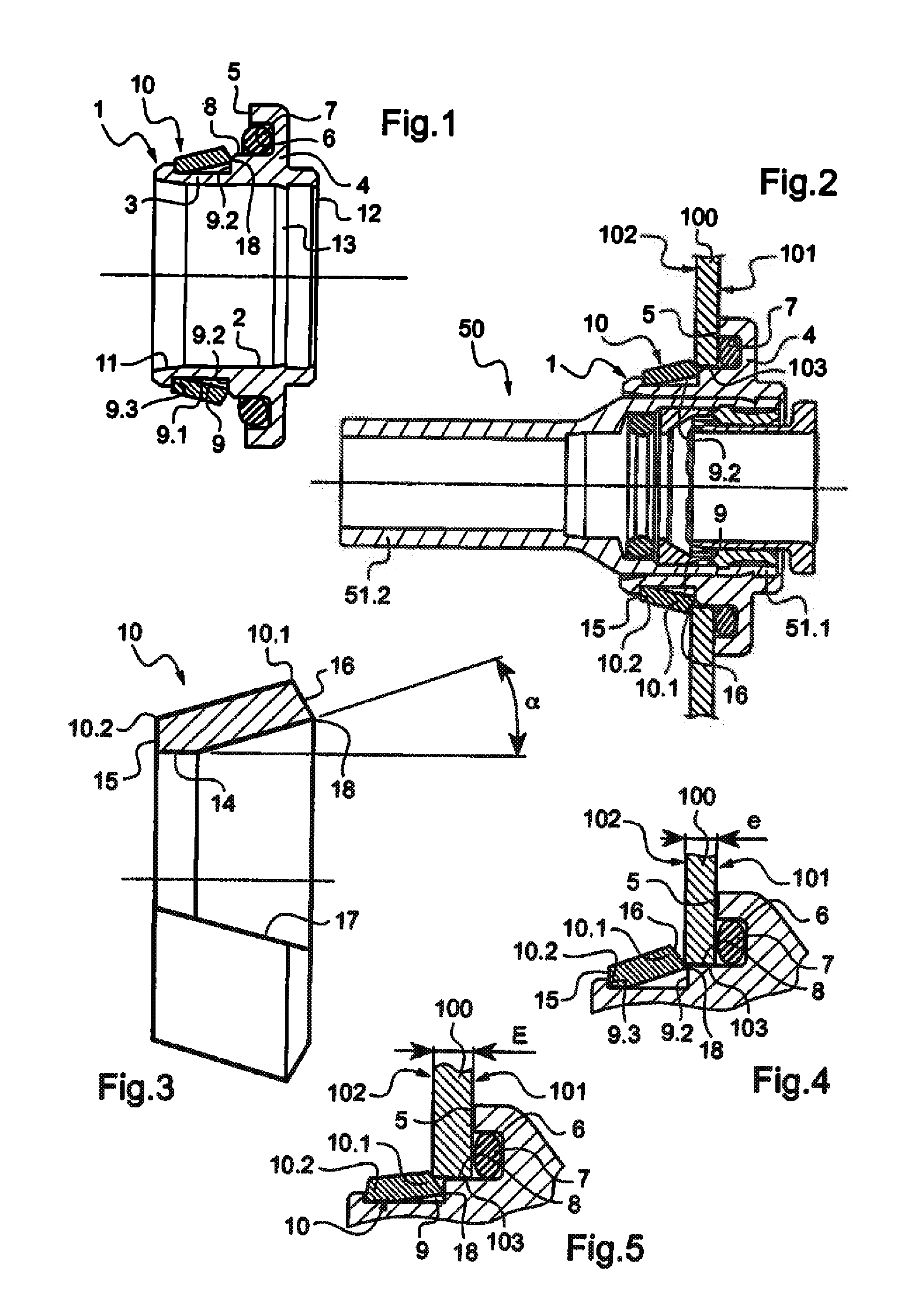
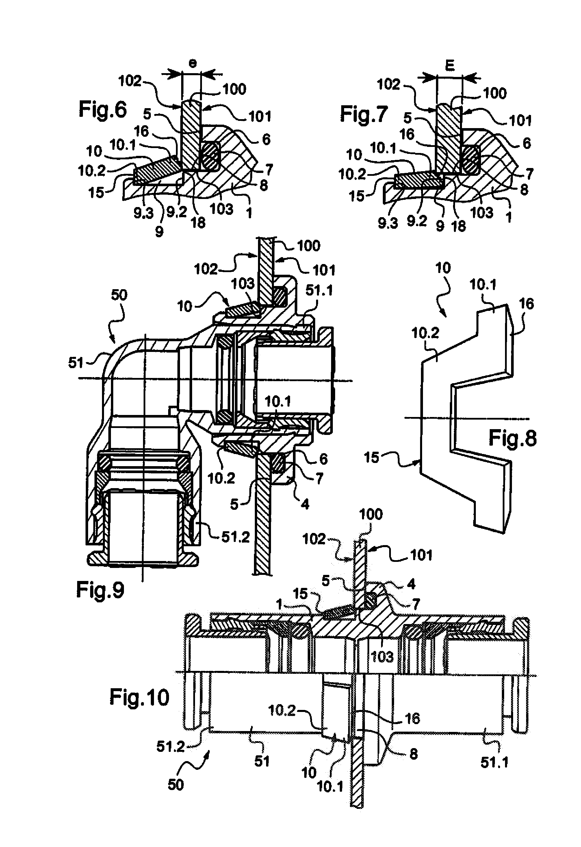
[0031]The anchor device of the invention is described herein in application to fastening a coupling designated by overall reference 50 to a wall 100 that has a first face 101 and a second face 102 opposite from the first face. The wall 100 is provided with an opening 103 defined by a side surface extending between the faces 101 and 102.

[0032]With reference to FIG. 2, the coupling 50 includes a tubular body 51 axially subdivided into a connection segment 51.1 for connecting to a first member of a fluid circuit, and a connection se ent 51.2 for connecting to a second member of the fluid circuit. These connections are known and are not therefore described in detail herein. Such connections are arranged to connect the members to the coupling instantaneously or otherwise, and releasably or otherwise. The body 51 is provided externally with the anchor device.

[0033]With reference to FIGS. 1 to 5, the anchor device includes a sleeve that is designated by overall reference 1, that is of tubu...


PUM


Abstract

An anchor device for anchoring an element such as a coupling in an opening in a wall the device including a sleeve for receiving the element, the sleeve being externally provided with a shoulder for bearing against a first face of the wall, and with an anchor member facing the shoulder having a portion that is resiliently movable between a laterally projecting position and a retracted position. The anchor member is a frustoconical ring received in a groove in the outside of the sleeve, the ring having larger end facing the shoulder with a sloping surface which forms the resiliently movable portion and which bears in the laterally projecting position against a zone of intersection between a side surface of the opening and a second face of the wall.

Description

CROSS-REFERENCE TO RELATED APPLICATIONS[0001]This application is a continuation of co-pending International Application No. PCT / FR2009 / 001479, filed Dec. 23, 2009, which designated the United States, and which claims priority to French Application No. 09 00144, filed Jan. 14, 2009, the disclosure of each of which is expressly incorporated herein by reference.BACKGROUND OF THE INVENTION[0002]The present invention relates to an anchor device for anchoring an element in an opening in a wall. For example, the element may be a coupling for connecting together two members of a fluid circuit such as members for delivering or for receiving fluid, and, for example, pipes, a manifold, an actuator, a flow-rate regulator or a pressure regulator, etc. The invention also provides such a coupling.[0003]Anchor devices are employed for anchoring an element in an opening in a wall having a first face and a second face that are opposite from each other. Such devices generally include a sleeve for rece...

Claims


Application Information

Patent Timeline
Patent Type & Authority Applications(United States)
IPC IPC(8): F16B17/00
CPCF16B21/086F16C1/107F16L5/027Y10T403/7075H01R13/745H02G3/0675F16L37/008
Inventor LE QUERE, PHILIPPE
Owner PARKER HANNIFIN FRANCE
Why Eureka
Try Eureka