Eureka AIR delivers breakthrough ideas for toughest innovation challenges, trusted by R&D personnel around the world.

Thermally loaded, cooled component

Active Publication Date: 2011-12-29
ANSALDO ENERGIA SWITZERLAND AG
View PDF16 Cites 2 Cited by
  • Summary
  • Abstract
  • Description
  • Claims
  • Application Information

AI Technical Summary

Benefits of technology

[0010]An aspect of the invention is to provide a thermally loaded, cooled component which avoids the described disadvantages of known components and is characterized by intensified cooling, which is associated with lower cost, in critical regions.

Problems solved by technology

The tapped-off cooling medium is either lost—in an open cooling system—or is returned to the steam cycle—in a closed cooling cycle, wherein, however, some energy losses typically arise.
Even if a highly-complex cooling system is provided inside the component which is to be cooled, which in the case of production can be associated with high costs, certain regions, such as corners inside the component which with regard to effective cooling still constitute a challenge, and which on account of local effects such as oxidation, creep or premature crack development may constitute a service-life problem, still remain.

Method used


Image

  • Thermally loaded, cooled component
  • Thermally loaded, cooled component
  • Thermally loaded, cooled component

Examples


Embodiment Construction

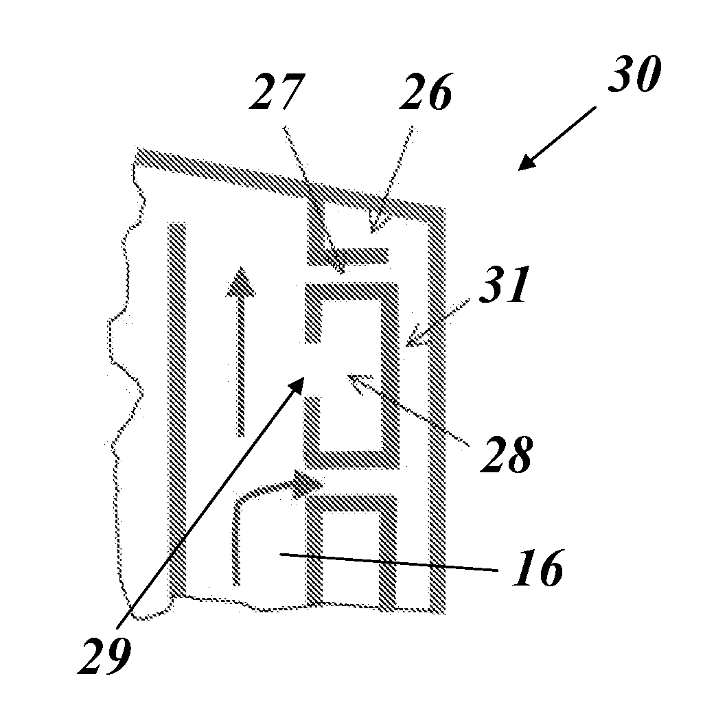
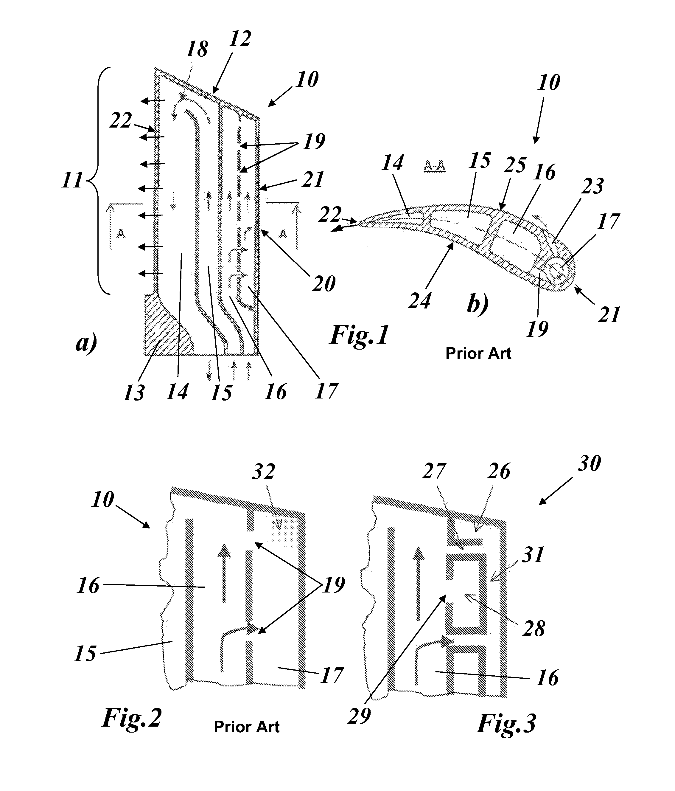
[0016]In one embodiment, at least one Helmholtz resonator is in hydraulic communication with the cooling system and is excited into vibrations by means of the flowing cooling medium itself.

[0017]In another embodiment, the at least one Helmholtz resonator is integrated into the cooling system.

[0018]In another embodiment, a plurality of Helmholtz resonators are arranged next to each other, and in the Helmholtz resonators are hydraulically interconnected in each case by means of a connecting passage for forming an acoustic heat pump.

[0019]In another embodiment, the Helmholtz resonator(s) is (are) integrated into the component, and in that the Helmholtz resonator(s) is (are) arranged in the component in regions with particularly high thermal loading.

[0020]In a further embodiment the component is part of a heat-generating electric device, especially a generator, a motor or a high-energy electronic system.

[0021]In another embodiment the component is part of a heat engine, especially a ste...


PUM


Abstract

A thermally loaded, cooled component thermally coupled to a cooling system configured to receive a gaseous cooling introduced in a forced manner from outside that flows through the cooling system so as to absorb and transport heat away from the component as a result of thermal contact with the component. The component includes at least one Helmholtz resonator configured to improve thermal contact between the cooling medium and the component.

Description

CROSS REFERENCE TO RELATED APPLICATIONS[0001]This application claims priority to Swedish Patent Application No. 01040 / 10, filed Jun. 25, 2011, which is hereby incorporated by reference herein in its entirety.TECHNICAL FIELD[0002]The present invention relates to the field of cooling of thermally loaded components.BACKGROUND OF THE INVENTION[0003]An effective cooling of gas-turbine components which come into contact with the hot gas of the turbine, such as rotor blades, stator blades or combustor parts, is an important element for controlling the service life and the performance of the machine. Thus, for example air, which is tapped off at the compressor and guided to the hottest points of the gas turbine, is directed through the rotor and the casing. In this way, hot regions of the rotor and of the casing are also cooled, which particularly in the case of the latest generations of high-performance gas turbines is absolutely necessary for these components for achieving the desired ser...

Claims


Application Information

Patent Timeline
IPC IPC(8): F01D5/18F28D15/00
CPCF01D5/187F05D2260/221Y02T50/676F05D2260/963Y02T50/60
Inventor SZWEDOWICZ, JAROSLAW LESZEKIRMISCH, STEFAN
Owner ANSALDO ENERGIA SWITZERLAND AG
Why Eureka
Eureka Blog
Learn More