Catheter assembly with seal member

a technology of seal member and catheter, which is applied in the field of catheter assembly with seal member, can solve the problems that none seems to have garnered commercial acceptance, and achieve the effect of improving the hemostasis seal arrangemen

Active Publication Date: 2011-12-29
SMITHS MEDICAL ASD INC
View PDF3 Cites 82 Cited by
  • Summary
  • Abstract
  • Description
  • Claims
  • Application Information

AI Technical Summary

Benefits of technology

The present invention provides catheter assemblies with improved hemostasis seal arrangements which are aimed at addressing drawbacks of previously proposed catheter assembly designs. To that end, and in accordance with one feature of the present invention, a rigid actuator extends proximally in the interior cavity from the catheter hub distal end to a free end having an enlarged proximal flange. The enlarged proximal flange may advantageously define a barb. In accordance with a further feature of the present invention, a seal member is disposed in the interior cavity of the catheter hub including a membrane and a distal portion extending distally from the membrane to a sealing outlet bore with the distal portion having an actuator cavity formed between the membrane and the sealing outlet bore so as to receive the free end of the actuator therein through the sealing outlet bore. The actuator cavity may advantageously have a narrowed portion that defines an hourglass shape thereto such that with the actuator extending through the sealing outlet bore into the actuator cavity, a surface of the proximal flange engages against the narrowed portion of the actuator cavity. The foregoing features provide a reliable seal between the seal member and the actuator while also providing a reliable hold of the seal member to the actuator.

Problems solved by technology

While various designs of catheter assemblies with hemostasis seals have been proposed, none seems to have garnered commercial acceptance.

Method used


Image

  • Catheter assembly with seal member
  • Catheter assembly with seal member
  • Catheter assembly with seal member

Examples


Embodiment Construction

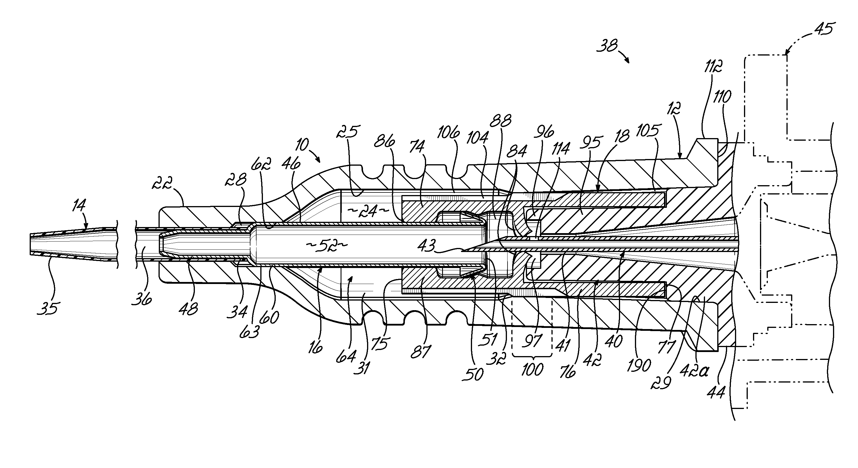
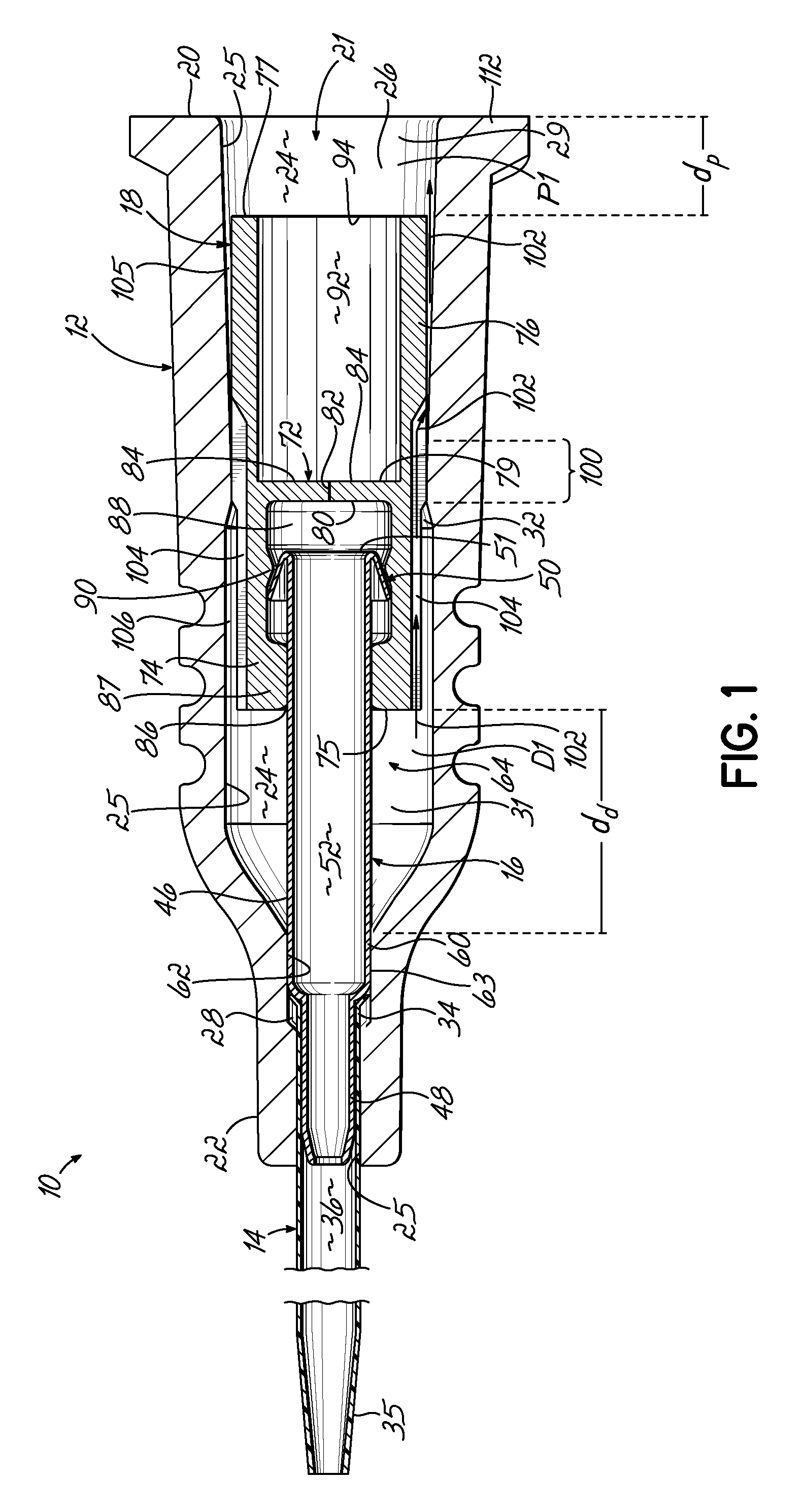
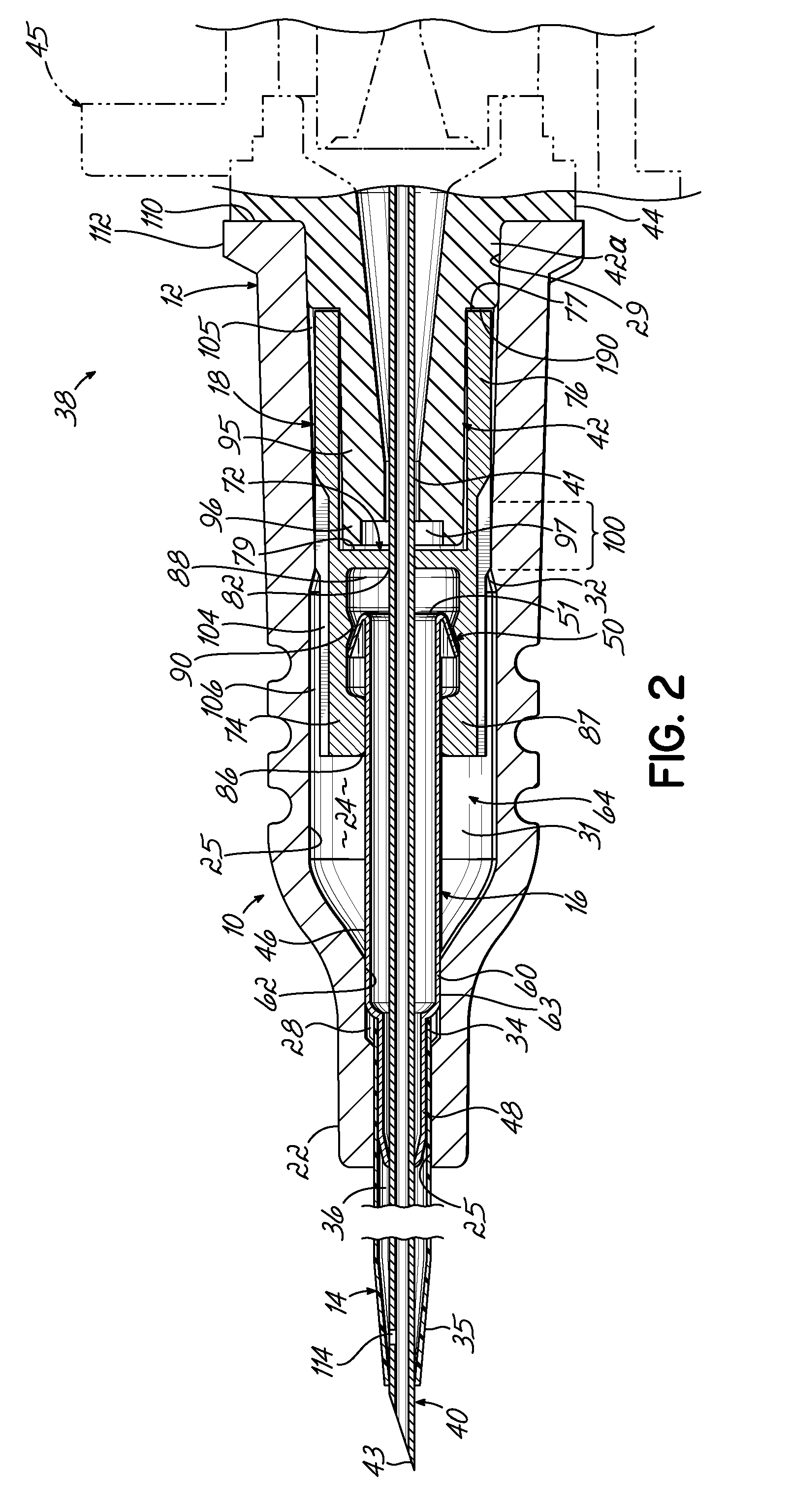
In reference to FIG. 1, a catheter assembly 10 in accordance with various features of the present invention includes a catheter hub 12, a catheter tube 14 secured to and extending distally of the catheter hub 12, an actuator 16 secured to the catheter hub 12 and extending axially therewithin, and a seal member 18 disposed in the catheter hub 12 and movably supported on the actuator 16. The seal member 18 is axially shiftable relative to the actuator 16, such as by sliding axially therealong, between a closed or sealed position shown in FIG. 1 and an opened or actuated position (shown, for example, in FIG. 10). In the closed position, the catheter hub 12 is substantially sealed off from the catheter tube 14 such that blood flow into the catheter hub 12 is restricted. In the opened position, however, and as will be discussed in more detail below, the seal member 18 is pushed over the actuator 16 such that the catheter hub 12 and catheter tube 14 are in open fluid communication.

The cat...


PUM

PropertyMeasurementUnit
lengthsaaaaaaaaaa
lengthsaaaaaaaaaa
lengthsaaaaaaaaaa

Abstract

A catheter assembly includes a catheter hub defining an interior cavity and a catheter tube extending distally thereof. A rigid actuator extends proximally in the interior cavity and supports a seal member thereon. The seal member includes a central membrane, a distal portion, and a proximal portion. An hourglass shaped actuator cavity is formed in the distal portion and receives a barbed end of the actuator. The outer surface of the seal member is in partial circumferential engagement with the catheter hub to define an air path that allows fluid communication between areas of the interior cavity distal and proximal of the seal member. A punch tool is provided to form a tri-slit in the membrane of the seal member. The seal member may be configured for multi-use and include a biasing member that moves the seal member to force the membrane back over the actuator to close the membrane.

Description

TECHNICAL FIELDThe present invention relates to over-the-needle catheters such as peripheral intravascular catheters or PIVC's and, more particularly, to a catheter assembly used with such catheters having a seal disposed in a hub thereof for enhanced blood control.BACKGROUNDBy way of background, conventional PIVC's include a catheter assembly, typically having a catheter hub and a catheter tube extending distally thereof, and a needle assembly mounted together in an over-the-needle fashion. The needle assembly typically includes a needle hub or support and a needle cannula extending distally thereof and, in a ready position of the PIVC, extending through the catheter tube to expose a sharp tip thereof distal of the tube and used to penetrate tissue for insertion of the catheter tube within the vascular system of a patient. Once the catheter tube is disposed within the vasculature, the needle cannula is withdrawn proximally from the catheter assembly and the catheter assembly remain...

Claims


Application Information

Patent Timeline
Patent Type & Authority Applications(United States)
IPC IPC(8): A61M25/18B23P17/04A61B17/34
CPCA61M25/0097A61M25/0606Y10T29/49826A61M25/0102A61M25/0014Y10T29/4987Y10T29/49872A61M25/06A61M39/06A61M25/0009A61M25/0618A61M25/0693
Inventor GORAL, DAVID J.ROEHL, CHRISTOPHER D.MUSKATELLO, JAMESMUNAVALLI, MAHESHMICHAUD, JOCELYN C.
Owner SMITHS MEDICAL ASD INC
Why Eureka
Try Eureka