Positional adjusting mechanism for a cutting insert

a technology of positioning adjustment and cutting insert, which is applied in the direction of cutting inserts, manufacturing tools, shaping cutters, etc., can solve the problems of disadvantage unsymmetrical slotted stop body, and respect to the precision of the system, and achieve the effect of exceptional high precision

Inactive Publication Date: 2003-09-16
SANDVIK INTELLECTUAL PROPERTY AB
View PDF12 Cites 29 Cited by
  • Summary
  • Abstract
  • Description
  • Claims
  • Application Information

AI Technical Summary

Benefits of technology

A primary object of the present invention is to provide a positional adjusting mechanism of the kind defined in the introduction, which can adjust the position of the cutting insert with exceptionally high precision.
Another aim of the present invention is that the positional adjusting mechanism should comprise as few components as possible as well as in other respects be structurally simple.
An additional aim of the present invention is that the positional adjusting mechanism should be well defined, i.e., rigid, in order to obtain maximum repetitive accuracy when installing the cutting inserts included in the tool.

Problems solved by technology

Furthermore, the slotted stop body is unsymmetrical, which means that it has to be mounted by means of a separate clamping part.
An additional disadvantage is that there is a play between the stop body and the bushing, which is of disadvantage with respect to the precision of the system.
This is disadvantageous to the precision of the system.
Nor is the bushing secured against axial movement that may be caused by high centrifugal forces in connection with high rotational speeds.

Method used


Image

  • Positional adjusting mechanism for a cutting insert
  • Positional adjusting mechanism for a cutting insert
  • Positional adjusting mechanism for a cutting insert

Examples


Embodiment Construction

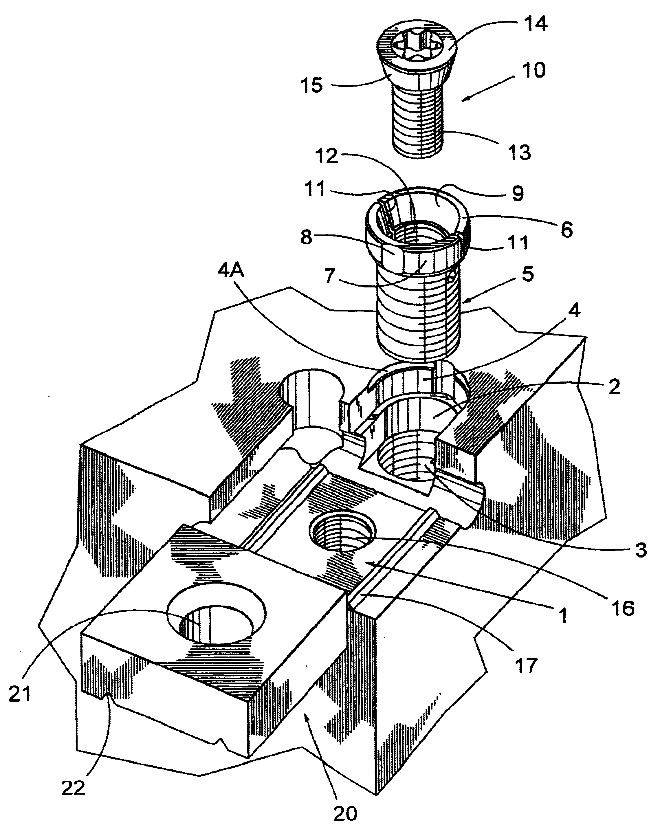
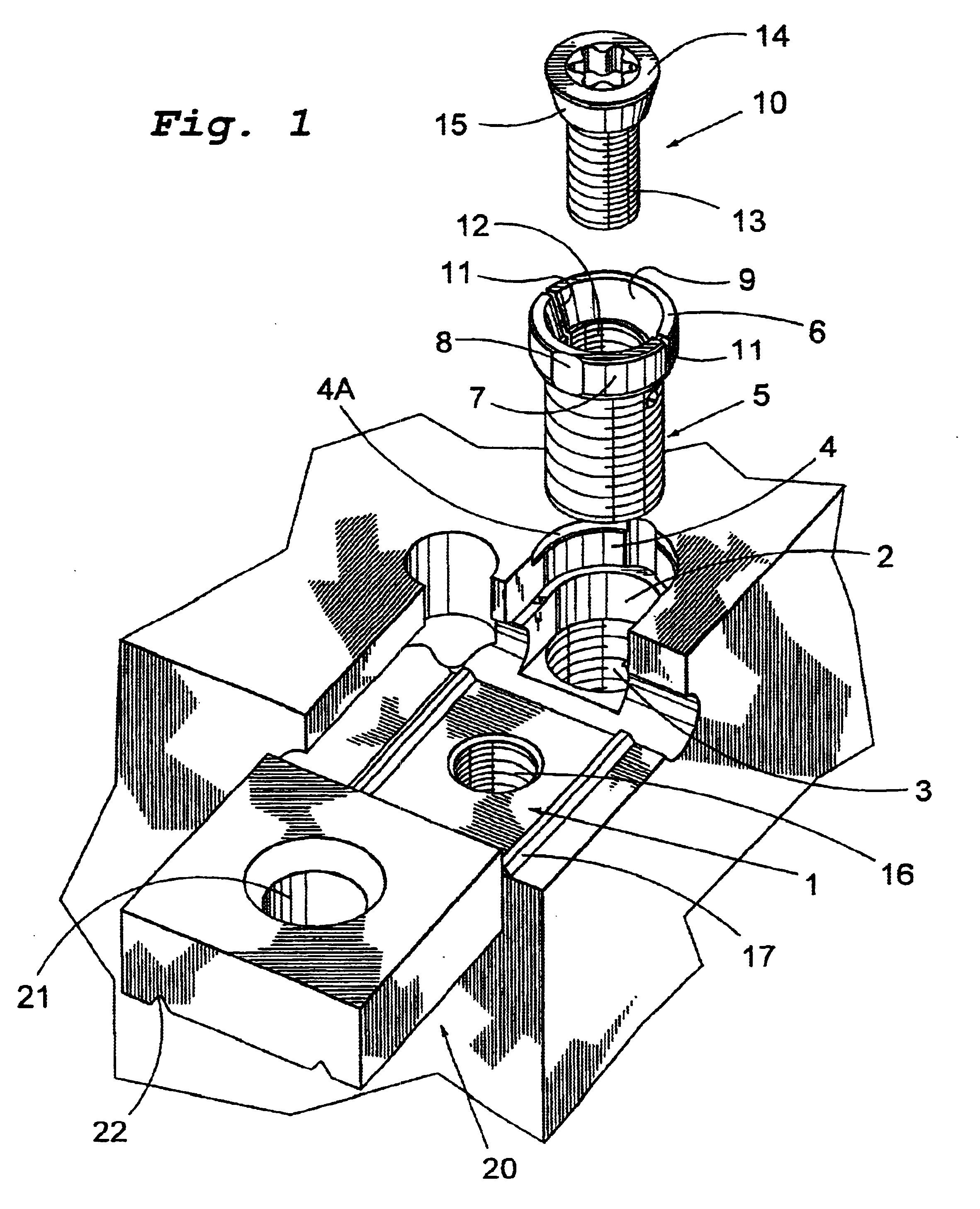
FIG. 1, a cutting seat 1 of a milling cutter is shown, a first cylindrical hole 3 being arranged adjacent to said cutting seat 1. As is indicated in FIG. 1, a generally cylindrical threaded bushing 5 is intended to be mounted in said first hole 3, whereby the assembly of the threaded bushing 5 may take place thanks to the threaded bushing 5 being provided with an external thread, which cooperates with an internal thread of the first hole 3. The threaded bushing 5 is, at the slotted upper end thereof in FIG. 1, provided with a collar 6, which has an external cylindrical surface 7 having a diameter larger than the external diameter of the rest of the threaded bushing 5. On the external cylindrical surface 7, two diametrically situated facets 8 are arranged, only one of which being seen in FIG. 1. On the inside thereof, the collar 6 has a conical surface 9, which is intended to cooperate with an adjusting screw 10 included in the positional adjusting mechanism according to the present ...


PUM

PropertyMeasurementUnit
displacementaaaaaaaaaa
diameteraaaaaaaaaa
frictionaaaaaaaaaa

Abstract

A positional adjusting mechanism for a cutting insert in a tool for chip removing machining, preferably a milling cutter. The positional adjusting mechanism includes a hole formed in the tool body adjacent to the cutting seat which receives the cutting insert. A slotted bushing is mounted in that hole. An adjusting screw is received in the bushing to expand an upper end of the bushing. In the mounted state of the bushing in its hole, contact occurs between an upper part of the bushing and a support surface of the tool body which urges the bushing laterally in its hole to eliminate lateral play and thus stabilizes the bushing.

Description

This application claims priority under 35 U.S.C. .sctn..sctn.119 and / or 365 to Patent Application Ser. No. 0002407-5 filed in Sweden on Jun. 27, 2000, the entire content of which is hereby incorporated by reference.1. Technical Field of the InventionThe present invention relates to a positional adjusting mechanism for a cutting insert in a tool for chip removing machining, preferably a milling cutter, which positional adjusting mechanism comprises a first hole recessed in the tool body in connection with a cutting seat for the cutting insert, a slotted bushing mounted in said hole as well as an adjusting screw received in said bushing. The invention also relates to a tool, which is provided with a positional adjusting mechanism according to the present invention.2. Prior ArtAn adjustable stop for a cutting insert is previously known from International Publication WO 98 / 43766, said stop comprising a slotted stop body in the upper part thereof, which is provided with a laterally protr...

Claims


Application Information

Patent Timeline
Patent Type & Authority Patents(United States)
IPC IPC(8): B23B27/16B23C5/24
CPCB23B27/1655B23B2200/165B23B2205/12Y10T407/1914Y10T82/10Y10T407/1912B23B2205/125B23C5/26
Inventor ENQUIST, LARS-ERIK
Owner SANDVIK INTELLECTUAL PROPERTY AB
Why Eureka
Try Eureka