Lateral Spondylolisthesis Reduction Cage
- Summary
- Abstract
- Description
- Claims
- Application Information
AI Technical Summary
Benefits of technology
Problems solved by technology
Method used
Image
Examples
first embodiment
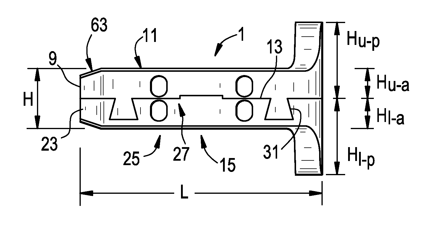
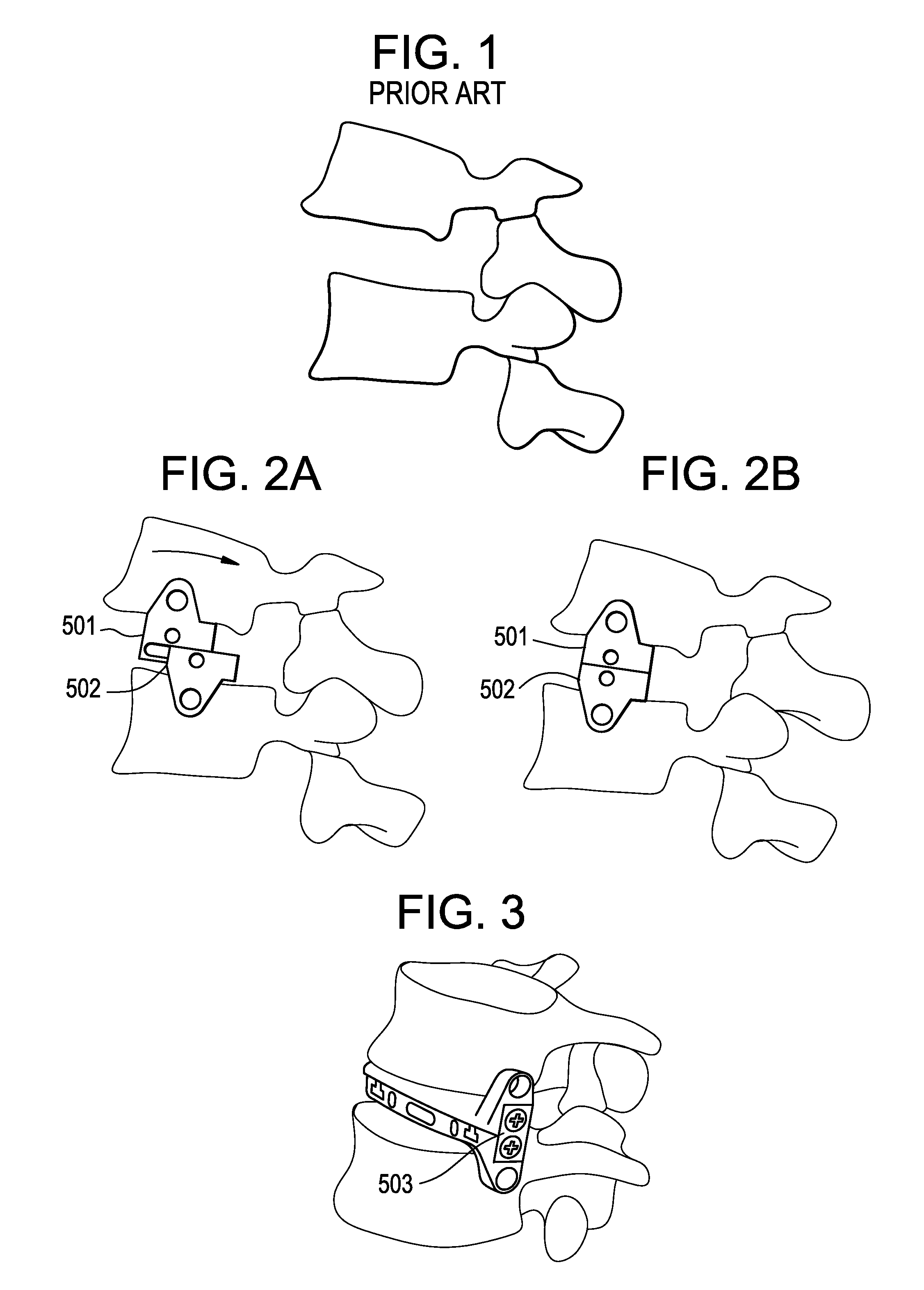
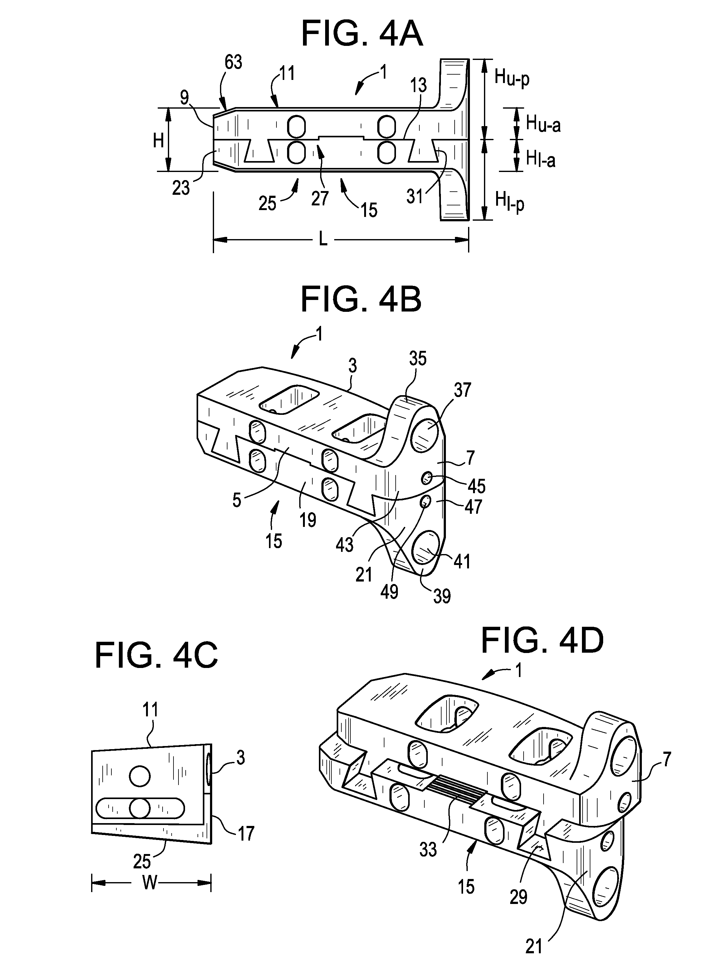
[0057]FIGS. 2a-2b and 3 disclose the implantation of a fusion device of the present invention, in which the cages 501,502 of the device are implanted into the disc space, brought together, and then locked in place with a locking plate 503. FIGS. 4a-4d show various views of the intervertebral fusion device of the present invention. FIGS. 4e-4f show various views of the cages of an intervertebral fusion device of the present invention locked with a locking plate.
[0058]FIG. 2a and FIG. 2b respectively show the relative positions of the fixed cage before and after alignment. In the FIG. 2b position, the cages have properly aligned the vertebral bodies, and thereby corrected the spondylolisthesis. The superior and inferior cages can also have features that provide or enhance the connection of the cages to the compressor. These features include recesses, pilot holes and threads located on the proximal walls of the two cages (and optionally extending therethrough) that receive mating featu...
second embodiment
[0083]In a second embodiment, and now referring to FIG. 8a-8d, the alignment means is rotary spreader-activated. FIGS. 8a-8d disclose how the cages of one embodiment of the present invention are aligned by a rotary spreader, and are locked by a particular locking plate. A modified spreader or shaver can be inserted into a space formed in the proximal end wall of the unaligned device. Rotating the spreader causes relative anterior-posterior movement of the upper cage vis-a-vis the lower cage to enable alignment of the cages and thereby intraoperative adjustment of a spondylosed functional spinal unit (FSU).
[0084]Now referring to FIG. 8b, optional locking plates can be employed to fix the device after the spondylolisthesis has been corrected. These plates are preferably inserted into bilateral, aligned, longitudinal recesses that extend across the interface of the aligned cages to provide inter-cage locking In some embodiments, these plates are locked into place via a snap-lock mechan...
third embodiment
[0092]In a third embodiment, and now referring to FIGS. 9a-9g, the attachment means is linkage activated. FIGS. 9a-9g disclose various views of a dual linkage embodiment of the present invention Single- or double-linkage can be used to correct spondylolisthesis by moving this cage from a pre-activated (FIG. 9a) to a post-activated state. (FIG. 9b) In some linkage embodiments, the anterior and posterior walls of the cages also function as linkage bars, providing for pivoting connection with both an upper wall component and a lower wall component to allow for relative anterior-posterior movement of the upper wall vis-à-vis the lower wall and thereby spondylolisthesis correction.
[0093]In some embodiments, and now referring to FIGS. 9c-9d, the upper portion of the upper wall and the lower portion of the lower wall extend outwardly, and transverse holes in these portions provide a means to fix the upper and lower walls to the respective lateral walls of the vertebral bodies.
[0094]In some...
PUM
 Abstract
Description
Claims
Application Information
 - R&D
- Intellectual Property
- Life Sciences
- Materials
- Tech Scout
- Unparalleled Data Quality
- Higher Quality Content
- 60% Fewer Hallucinations
Browse by: Latest US Patents, China's latest patents, Technical Efficacy Thesaurus, Application Domain, Technology Topic, Popular Technical Reports.
© 2025 PatSnap. All rights reserved.Legal|Privacy policy|Modern Slavery Act Transparency Statement|Sitemap|About US| Contact US: help@patsnap.com


