Six-degree-of-freedom precision positioning system

a positioning system and freedom technology, applied in the field of precision positioning system, can solve the problems of lowering positioning precision, lowering overall positioning precision, and not being suitable for applications, and achieve the effects of reducing power consumption, low power loss, and improving controllability of the platform

Inactive Publication Date: 2011-05-10
NAT TAIWAN UNIV
View PDF10 Cites 4 Cited by
  • Summary
  • Abstract
  • Description
  • Claims
  • Application Information

AI Technical Summary

Benefits of technology

[0008]A primary object of the present invention is to provide a six-degree-of-freedom precision positioning system that utilizes the properties of fluid to enhance the controllability of a platform and largely reduce the power consumption by electromagnetic coils, and thereby achieves the purpose of low power loss in the system.
[0009]Another object of the present invention is to provide a six-degree-of-freedom precision positioning system that has large travel distance, precise positioning ability, and simplified as well as economical structural design.

Problems solved by technology

However, the piezoelectric actuator allows only a limited travel distance, and is therefore not suitable for the applications that require a relatively large travel distance.
However, since the lead screw is subject to the backlash phenomenon and the friction between bearings, the overall positioning precision is obviously lowered.
On the other hand, the linear motor is subject to the ripple effects and the end-effects to thereby cause lowered positioning precision.
However, the first two systems are not suitable for use in some special environments, such as dust-free room, vacuum environment, etc.
While these two systems are theoretically and experimentally excellent, they still have some inherent defects that could not be easily overcome, such as low structural strength, complicated mechanism design, and relatively high power consumption.
However, this system involves in complicated and highly difficult fabricating procedures, and is therefore not easily widely accepted by related industrial fields.
While it is expected this system would be able to meet the requirement of high precision, the hardware mechanism design for this system is restricted by the inherent limitation in travel distance, and is therefore not suitable for applications involving a large travel distance.
However, a biggest disadvantage of this system is its relatively complicated mechanism design and high manufacturing cost.
Moreover, the system of Professor Menq has higher power consumption compared to the other two systems, and is therefore not economical for use.
In summary, the magnetic levitation positioning systems of prior art have one or more of the disadvantages of limited travel distance, complicated structural design, high manufacturing cost, and high power consumption.

Method used


Image

  • Six-degree-of-freedom precision positioning system
  • Six-degree-of-freedom precision positioning system
  • Six-degree-of-freedom precision positioning system

Examples


Embodiment Construction

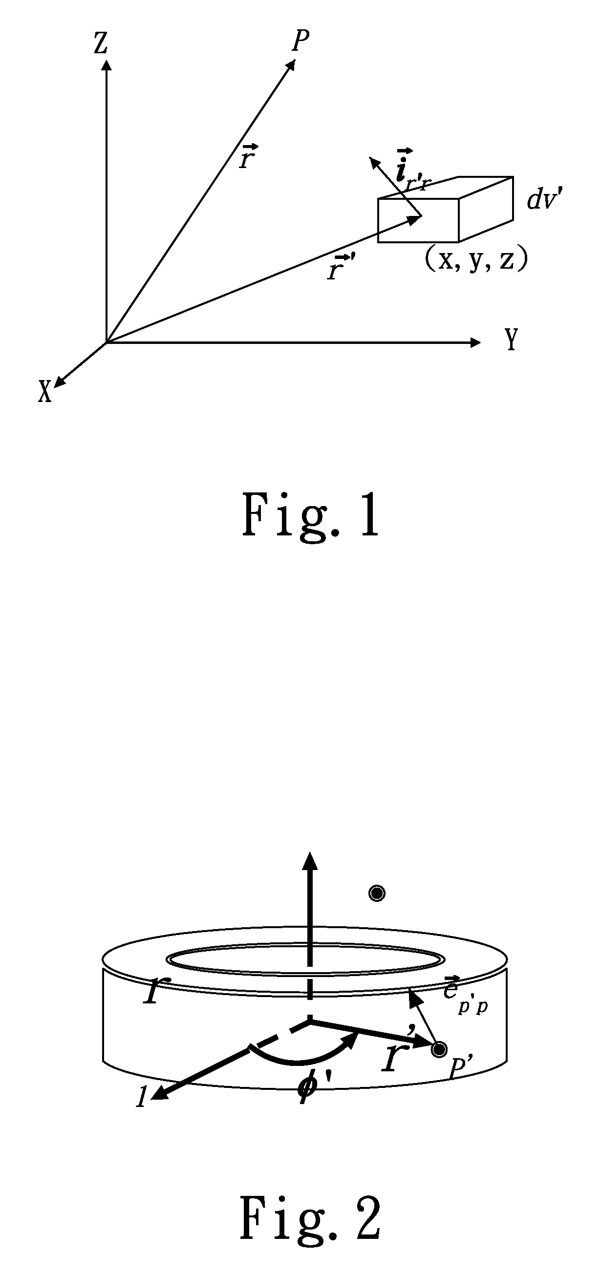
[0024]Please refer to FIG. 1. As a basic electromagnetism, the magnetic vector produced in a space by an object having an electric current flowed therethrough can be derived according to Biot-Savart Law and expressed by the following equation:

[0025]H⇀=14⁢π⁢∫v′⁢J⇀⁡(r⇀′)×i⇀r′⁢rr′-r2⁢⁢ⅆv′(1)

[0026]where, {right arrow over (r)} is the position vector of an observation point; {right arrow over (r)}′ is the surface current position vector; {right arrow over (J)}({right arrow over (r)}′) is the density of current flowed through the coil; and {right arrow over (i)}r′r is the position vector of the observation point relative to the surface current.

[0027]The above equation (1) may be applied to a cylindrical electromagnet as that shown in FIG. 2, and to a rectangular electromagnet. In the case of a cylindrical electromagnet, the magnetic vector produced by the cylindrical electromagnet in the space can be expressed by the following equation:

[0028]H⇀cyl=14⁢π⁢∫-h1 / 2h1 / 2⁢∫02⁢π⁢∫r1r2⁢(NIcyl(r2-r1)...


PUM

PropertyMeasurementUnit
frequencyaaaaaaaaaa
magnetic polarityaaaaaaaaaa
travel distanceaaaaaaaaaa

Abstract

In a six-degree-of-freedom precision positioning system, magnetic force and fluid buoyancy are used to levitate a platform, and the non-contact magnetic force between electromagnets and magnets forms a main driving force for the platform. Therefore, no friction is present in the system and no lubricating mechanism is needed for the system. Moreover, in the system, electric current is converted by electromagnets and magnets into a magnetic driving force without using any transmission gears. Therefore, the backlash phenomenon that is not easily controllable in the conventional servo positioning systems is avoided. The system has simplified structure without the need of complicated fabrication, and utilizes the properties of fluid to achieve low power consumption, high precision positioning, and fast response.

Description

FIELD OF THE INVENTION[0001]The present invention relates to a precision positioning system for the control or regulation of non-electric variables, and more particularly to a six-degree-of-freedom precision positioning system that utilizes feedback to control position or direction.BACKGROUND OF THE INVENTION[0002]A high-precision positioning system plays more and more important role in nowadays high technological fields, such as IC manufacturing process, home entertainment systems, including DVD and VCD players, etc. Currently, there are already developed many precision positioning technologies that adopt, for example, a piezoelectric actuator, which not only enables a definition as high as 10 nanometers within a travel distance of only 10 micrometers, but also has fast response. However, the piezoelectric actuator allows only a limited travel distance, and is therefore not suitable for the applications that require a relatively large travel distance. To meet the requirement for lo...

Claims


Application Information

Patent Timeline
Patent Type & Authority Patents(United States)
IPC IPC(8): H01F1/00
CPCG03F7/70725G03F7/70758H02N15/00G03F7/70816Y10T74/20348
Inventor FU, LI-CHENHUANG, SHENG-CHIHHUNG, SHAO-KANGCHEN, MEI-YUNG
Owner NAT TAIWAN UNIV
Why Eureka
Try Eureka