Decorative material and decorative sheet

a technology of decorative sheets and decorative sheets, applied in the direction of roads, instruments, traffic signals, etc., can solve the problems of grain depression, doctor streaks, and insufficient scraping of the parts, and achieve the effects of proper flow ability, easy and continuous production, and viscosity and thixotropic properties

Inactive Publication Date: 2010-04-08
DAI NIPPON PRINTING CO LTD
View PDF6 Cites 3 Cited by
  • Summary
  • Abstract
  • Description
  • Claims
  • Application Information

AI Technical Summary

Benefits of technology

[0133]The convex-concave pattern by conventional relief printing is formed concerning not to deteriorate the height of the convex part by maintaining the relief shape of the convex part, formed as the printed part, as much as possible. Therefore, in the case of the conventional relief printing, the thixotropic property is better to be as high as possible. On the other hand, the present invention is based on a different concept from that of the conventional relief printing. Unlike the conventional relief printing, ink is intentionally flowed in order to form the convex pattern. That is thoroughly out of the idea of conventional relief printing, and thus, the present invention is accomplished based on the finding of advantageous effects in the field which are out of the conceptual range of the conventional relief printing.
[0134]The viscosity and thixotropic property of the ink can be adjusted properly by: binder resin (cross-link curing resin) of the ink; inorganic fillers such as a fine powder silica as a thixotropic agent; inorganic fillers such as silica, alumina, kaolin, and calcium carbonate; organic fillers such as resin beads; use or not of a diluting solvent; their adding amounts; and the temperature at the time of ink printing (and until the ink is cured). It is also effective to add two types of fillers with different average particle diameter at the time of addition of the filler. Specifically: fine particle silica powder with an average particle diameter of nm order is used in combination with a delustering silica powder with an average particle diameter around 5 to 20 μm; or a filler with a smaller average particle diameter is used in combination with a filler with a larger average particle diameter. Also, paying attention to the particle size distribution other than the average particle diameter, proper flow ability may be obtained.
[0135]In plane view of FIG. 2, a plane view shape of one example of the convex patterns 2 is shown. The convex pattern, as shown in FIG. 2, is a pattern composed of a large number of winding lines. FIG. 2 shows the patterns (printed parts are black parts) on a printing plate for forming the convex patterns by printing, and is a magnified drawing of an area of 5.25 cm length by 3.5 cm width (quadruple).
[0136]The plane view shape of the convex pattern is not particularly limited and may be formed depending on the uses. However, it is preferable to prevent a pattern, wherein the non-printed part is extremely wide as compared with the printed part that the printed parts are located in far apart to each other. That is because there is a limitation of the flow of the ink so that the non-printed parts may not be covered with the ink from the printed parts.
[0137]The plane view shape of the convex patterns may be a regular shape in addition to the random shape as exemplified in FIG. 2. For example, it may be corrugated shape, hair line shape and the like. The convex patterns in the plane view may be as lines, a continuous printed part which extends to the entire surface of the decorative sheet or the decorative plate, in addition to a plurality of respectively independent parts with limited area as exemplified in FIG. 2. They can be designed depending on the design expression.
[0138]The random shape is preferable from a viewpoint that the strength unevenness of the scratch resistance due to the convex pattern is not imparted, and that visually uneven impression is given to the convex patterns to result in visually even impression.

Problems solved by technology

The doctor streak occurs when a tip of the doctor blade is chipped off, a groove shaped damage (doctor damage) occurs across the tip, so that the ink of this part is not scraped off sufficiently, because the doctor blade is not worn evenly in its width direction.
However, particularly when the ink or coating liquid contain delustering agent such as delustering silica, the doctor streak is likely to occur.
However, a problem of grain depression is likely to occur.
Therefore, the coating process of the coating film layer or the overcoat layer is necessary in addition to the relief printing of the convex-concave pattern so that high cost in processing and high material cost are inevitable.
However, with such configuration, sufficient property cannot be obtained in applications in which scratch resistance or contamination resistance is required.
Therefore, contamination resistance of the decorative sheet is deteriorated as a whole, due to the poor contamination resistance of the lower layer (refer to FIG. 4).
On the other hand, when the delustering silica is added in order to adjust the luster of the surface, there is a problem that the doctor streak tends to occur.
Further, in case of using the ionizing radiation curing resin by itself, the surface thereof tends to have a strong luster and it is difficult to weaken the luster.
Therefore, the delustering agent must be added in the applications in which the strong luster is not wanted, so that improvement of the doctor streak and making the manufacturing easier are inevitable problems.

Method used


Image

  • Decorative material and decorative sheet
  • Decorative material and decorative sheet
  • Decorative material and decorative sheet

Examples


first embodiment

(1) First Embodiment

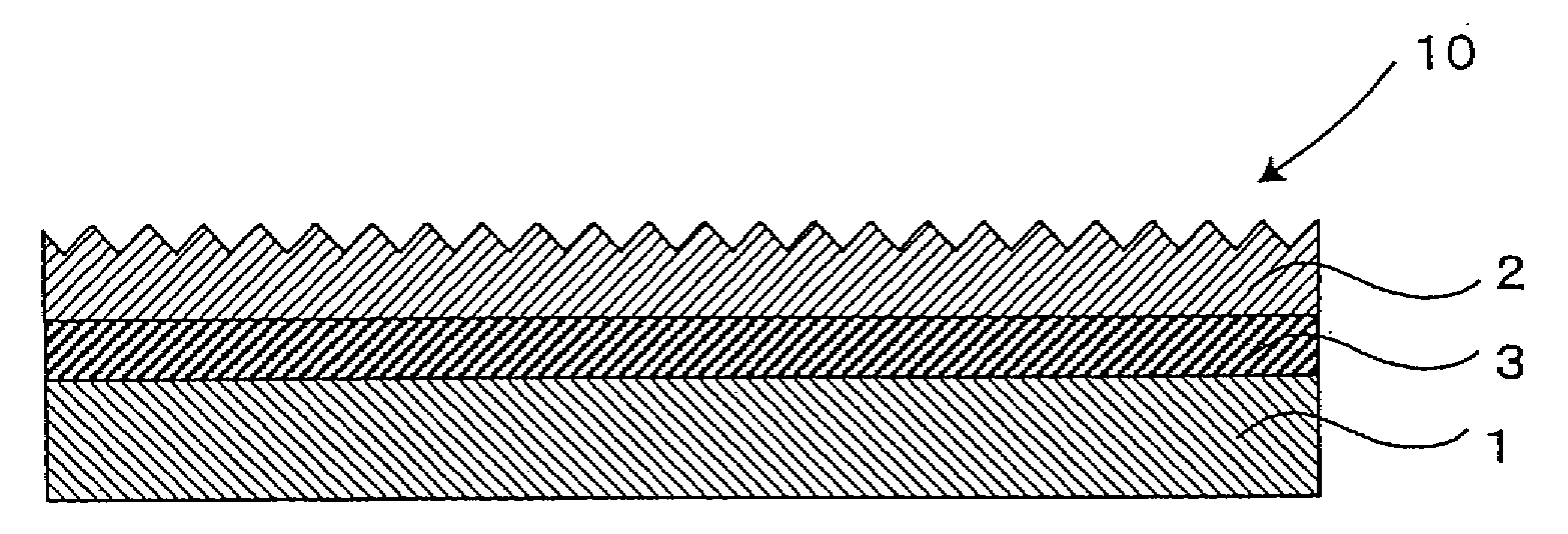
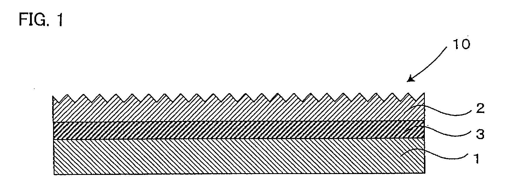
[0052]At first, the first embodiment of the decorative material of the present invention will be explained. For example as shown in FIG. 1, the first embodiment of a decorative material of the present invention comprises at least: a base material 1; and a luster adjusting resin layer 2, formed thereon, which is formed of a cross-linked cured material of an ionizing radiation curing resin containing delustering silica, and for the delustering silica contained in the luster adjusting resin layer 2, the delustering silica, whose surface is treated with fatty acid based wax, is used.

[0053]Hereinafter, the respective components of the decorative material of this embodiment will be explained.

[Luster Adjusting Resin Layer]

[0054]At first, the luster adjusting resin layer 2 is a layer for providing surface physical properties such as abrasion resistance to the decorative material surface and adjusting the surface luster of the decorative material to lower the luster or to...

second embodiment

(2) Second Embodiment

[0094]Next, the second embodiment of a decorative material of the present invention will be explained. As shown in FIG. 1, the second embodiment of a decorative material of the present invention comprises at least a base material 1 and a luster adjusting resin layer 2, formed thereon, which is formed of a cross-linked cured material of an ionizing radiation curing resin containing delustering silica, and the luster adjusting resin layer 2 further contains either of both of magnesium hydroxide and magnesium carbonate, in addition to the delustering silica.

[0095]Hereinafter, the respective components of the decorative material of this embodiment will be explained.

[Luster Adjusting Resin Layer]

[0096]At first, the luster adjusting resin layer 2 is a layer for providing surface physical properties such as abrasion resistance to the decorative material surface and for adjusting the surface luster of the decorative material to lower the luster or to deluster the surfac...

example 1

[0183]First, by using a coloring ink using a nitrocellulose based resin as a binder resin, a decorative layer, which is also used as a screening layer, was formed on a base material, formed of a resin impregnated paper of basic weight of 50 g / m2, in a solid gray pattern for the entire surface by a gravure printing.

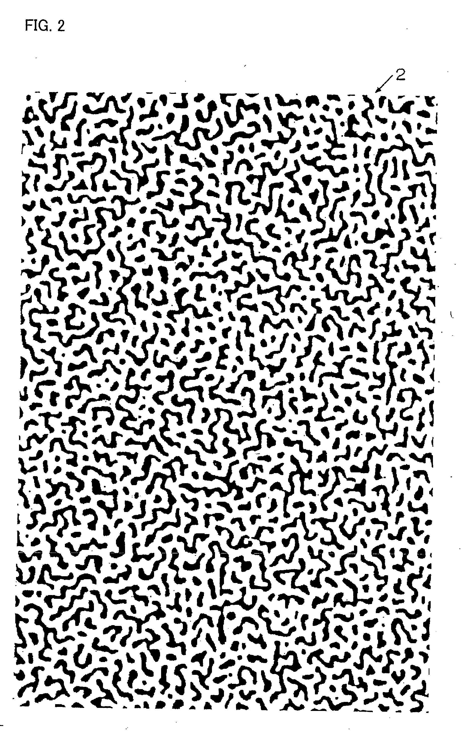
[0184]Next, by using a non-solvent ink formed of the below mentioned ionizing radiation curing resin composition, a predetermined decorative material was obtained as follows. After the gravure printing (relief printing) using a ceramic doctor and a gravure plate with a pattern as shown in a plane view in FIG. 2 (magnification), a luster adjusting resin layer, formed with a cross-link curing resin obtained by curing the ink with ionizing radiation, was provided on the decorative layer forming side. The luster of the decorative material was delustered by the luster adjusting resin layer, and a convex-concave surface design was imparted by the layer. Types of the luster adjus...


PUM

PropertyMeasurementUnit
particle diameteraaaaaaaaaa

Abstract

Realization of a configuration of decorative sheet, particularly a decorative paper, or a decorative material in which it is adhered, meaning: a grain depression is not visible; excellent in scratch resistance, also in contamination resistance; and three-dimensional design can be expressed. The configuration is realized by using delustering silica, whose surface is treated with a fatty acid based wax such as stearic acid, in a decorative material 10 in which a luster adjusting resin layer 2, formed of a cross-linked cured material of an ionizing radiation curing resin composition containing a delustering silica, is on base material 1.

Description

TECHNICAL FIELD[0001]The present invention relates to: a decorative sheet wherein grain depression is not recognizable, excellent in scratch resistance and in contamination resistance, three-dimensional design can be expressed and a surface thereof can be delustered; and method for manufacturing the same. The present invention also relates to a decorative material whose surface strength such as abrasion resistance is imparted by an ionizing radiation curing resin layer, and also, whose surface is delustered by delustering silica.BACKGROUND ART[0002]Decorative sheets using paper and resin sheet, or decorative materials such as decorative material in the form of plate, in which the above-mentioned decorative sheet is adhered to an adhered base material, are used in various uses such as construction interior and exterior materials. These decorative sheets and decorative materials, in general, are often required to have surface strength such as scratch resistance and the like. For the a...

Claims


Application Information

Patent Timeline
Patent Type & Authority Applications(United States)
IPC IPC(8): B32B3/30B05D1/28C08K3/26C08K3/22B32B27/20B44C5/04
CPCB32B27/20B44C5/0476Y10T428/24802Y10T428/24612Y10T428/25Y10T428/24355Y10T428/24372Y10T428/24479B32B3/30
Inventor ABE, KAZUHIROSHIBATA, TAKAYUKI
Owner DAI NIPPON PRINTING CO LTD
Why Eureka
Try Eureka