Inter-clock domain data transfer FIFO circuit

a data transfer circuit and clock domain technology, applied in the field of electronic data transfer devices and circuits, can solve the problems of increasing the latency of the interface, limiting the data transfer rate and latencies of asynchronous interconnects, and synchronizing to what is considered high-risk transfer, etc., and achieve the effect of low gate coun

Inactive Publication Date: 2011-12-29
KING FAHD UNIVERSITY OF PETROLEUM AND MINERALS
View PDF3 Cites 61 Cited by
  • Summary
  • Abstract
  • Description
  • Claims
  • Application Information

AI Technical Summary

Benefits of technology

The inter-clock domain data transfer FIFO circuit is a new circuit for transferring data between two clock domains of unrelated frequencies. With a relatively low gate count, it allows data transfer between the two clock domains at one data item per cycle of the lower of the two frequencies. Depending on the frequency difference between the data producer and the consumer, the initial latency could be as low as a fraction of a cycle, and no more than two cycles of the consumer's clock. The operation of this circuit has been verified using gate-level simulations for several ratios of clock frequencies.

Problems solved by technology

Also, due to the difficulty of globally synchronizing SoC components, Globally Asynchronous Locally Synchronous (GALS) systems have emerged.
The data transfer rates and latencies of asynchronous interconnects are limited due to the required handshaking.
Synchronization is limited to what is considered as high-risk transfers.
However, it increased the latency of the interface, since the pipeline has to be filled first before data can come out of it.
While this implementation is well suited for large buffers, it has a complex design and significant latency.

Method used


Image

  • Inter-clock domain data transfer FIFO circuit
  • Inter-clock domain data transfer FIFO circuit
  • Inter-clock domain data transfer FIFO circuit

Examples


Embodiment Construction

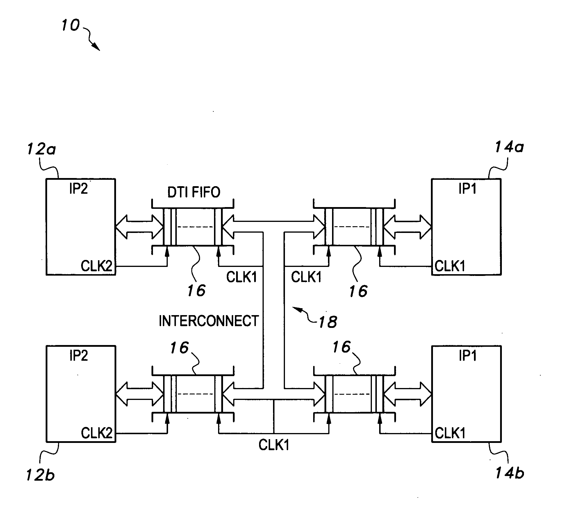
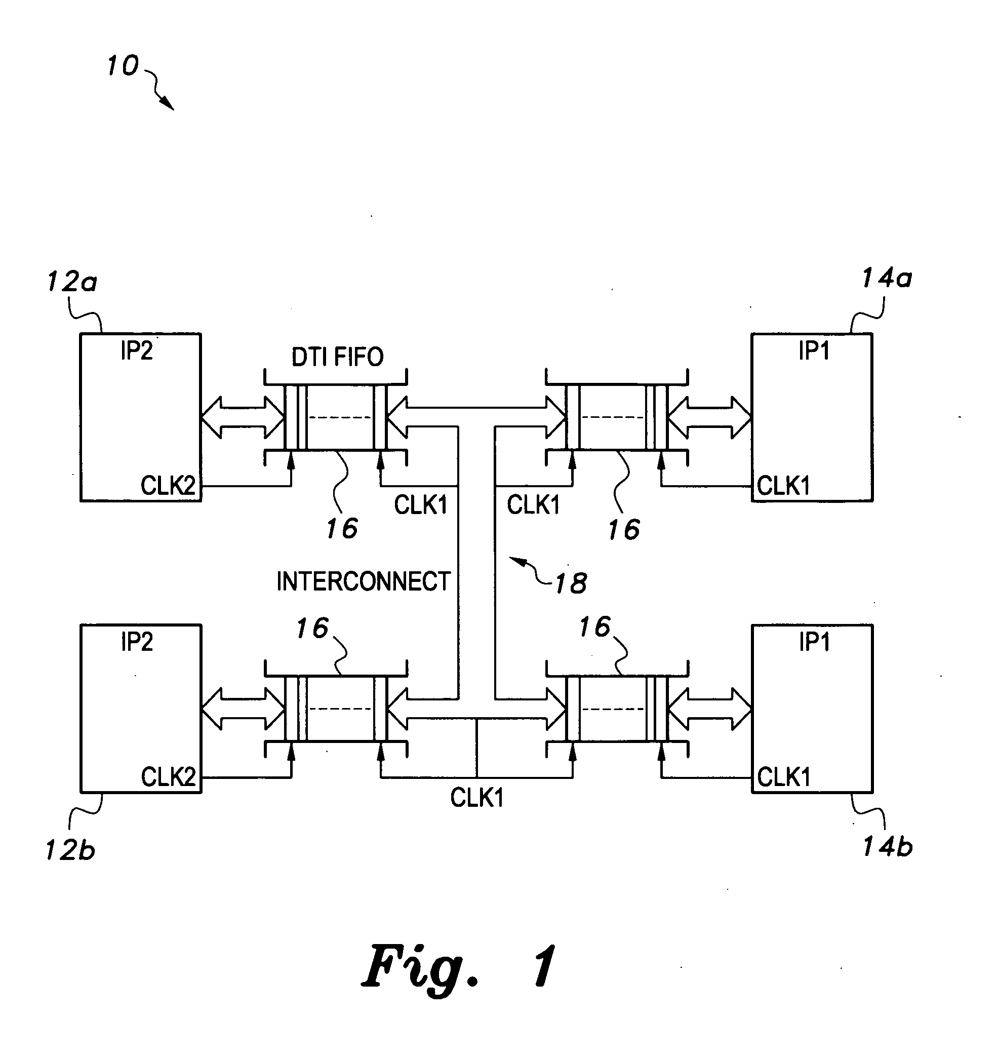
Referring to FIG. 1, an exemplary polysynchronous Globally Asynchronous Locally Synchronous (GALS) system 10 includes a data transfer interface (DTI) circuit having DTI FIFOs (inter-clock domain transfer FIFO circuits) 16, which allow data transfer between a data client producer and an on-chip interconnection medium, such as a Network-on-Chip (NoC). As shown in FIG. 1, the polysynchronous GALS system 10, which includes a fully synchronous interconnect medium 18 running at its own independent clock (CLKI), connects several arbitrarily and locally clocked IPs through the DTI FIFOs 16.

Each DTI FIFO 16 can be disposed within a polysynchronous system-on-chip (SoC) 10. A polysynchronous system represents an unrestricted form of a Globally Asynchronous Locally Synchronous System (GALS). Referring to the Intellectual Property modules (IP), upper IP module IP2 12a (interconnected with lower IP module IP2 12b) and upper IP module IP1 14a (interconnected with lower IP module IP1 14b) are each ...


PUM


Abstract

The inter-clock domain data transfer FIFO circuit provides a circuit that transfers data between two clock domains of unrelated frequencies. The gate count is kept relatively low, thereby allowing data transfer between the two clock domains at one data item per cycle of the lower of the two frequencies. Depending on the frequency difference between the data producer and consumer, the initial latency could be as low as a fraction of a cycle and no more than two cycles of the consumer's clock. The operation of the data transfer FIFO circuit has been verified using gate-level simulations for several ratios of clock frequencies.

Description

BACKGROUND OF THE INVENTION1. Field of the InventionThe present invention generally relates to electronic data transfer devices, circuits, and methods, and more particularly to an inter-clock domain data transfer FIFO circuit for regulating the transfer of data between two clock domains of unrelated frequency.2. Description of the Related ArtCurrently, Systems-on-Chip (SoCs) are constructed using a wide range of pre-designed intellectual property modules (IPs) that are integrated together with a communication medium (typically a system bus). Each IP may have different clock and communication needs. This, coupled with the ever increasing demands on shorter time-to-market, necessitates developing efficient design flows that can achieve time closure of the whole SoC in a short time while satisfying the communication needs of its various components. Several SoC bus standards have been developed requiring either asynchronous or synchronous IP interfaces.Due to the limitations of the afor...

Claims


Application Information

Patent Timeline
Patent Type & Authority Applications(United States)
IPC IPC(8): G06F5/06
CPCG06F5/14
Inventor ELRABAA, MUHAMMAD E.S.
Owner KING FAHD UNIVERSITY OF PETROLEUM AND MINERALS
Why Eureka
Try Eureka