Radiation detector

a detector and radiation technology, applied in the field of radiation detectors, can solve the problems of large reinforcement plate, large fpd, large detector, etc., and achieve the effect of few image defects

Inactive Publication Date: 2012-01-05
KONICA MINOLTA MEDICAL & GRAPHICS INC
View PDF6 Cites 28 Cited by
  • Summary
  • Abstract
  • Description
  • Claims
  • Application Information

AI Technical Summary

Benefits of technology

[0022]According to the present invention, there can be provided a compact radiation detector causing few image defects.

Problems solved by technology

In the technique described in the patent document 1, however, it was necessary to cover a scintillator layer with such a reinforcing plate, producing problems such that the reinforcing plate became larger and a flat panel detector (hereinafter, also denoted as FPD) also became larger.
Further, in the technique described in the patent document 2, there was produced a problem such that image defects were produced along with variation in temperature and such a problem was marked specifically when using a scintillator panel, while being brought into contact with an array substrate provided with a photoelectric conversion panel.

Method used


Image

  • Radiation detector
  • Radiation detector
  • Radiation detector

Examples


example 1

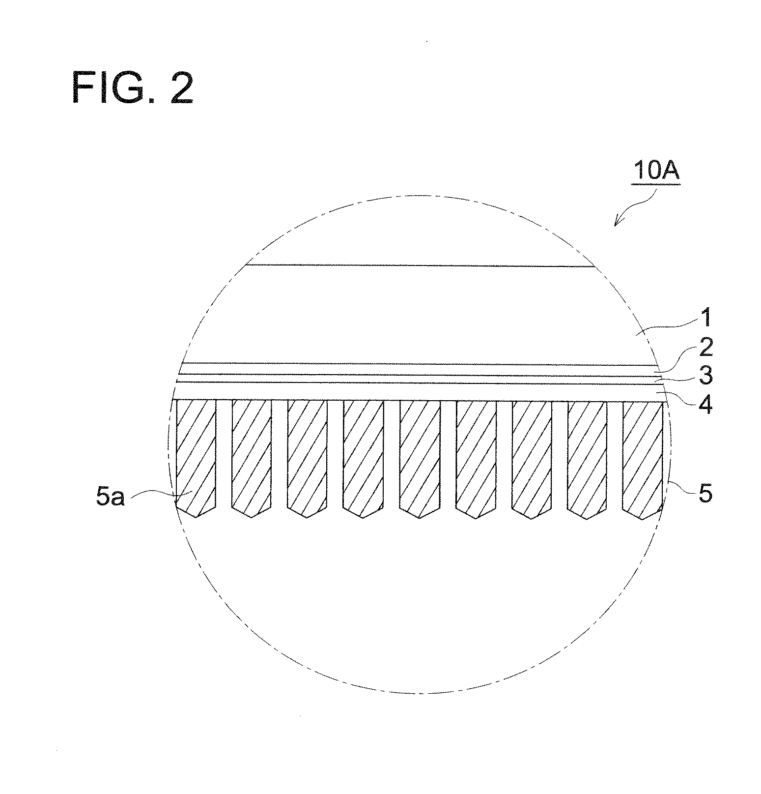
Preparation of Reflection Layer:

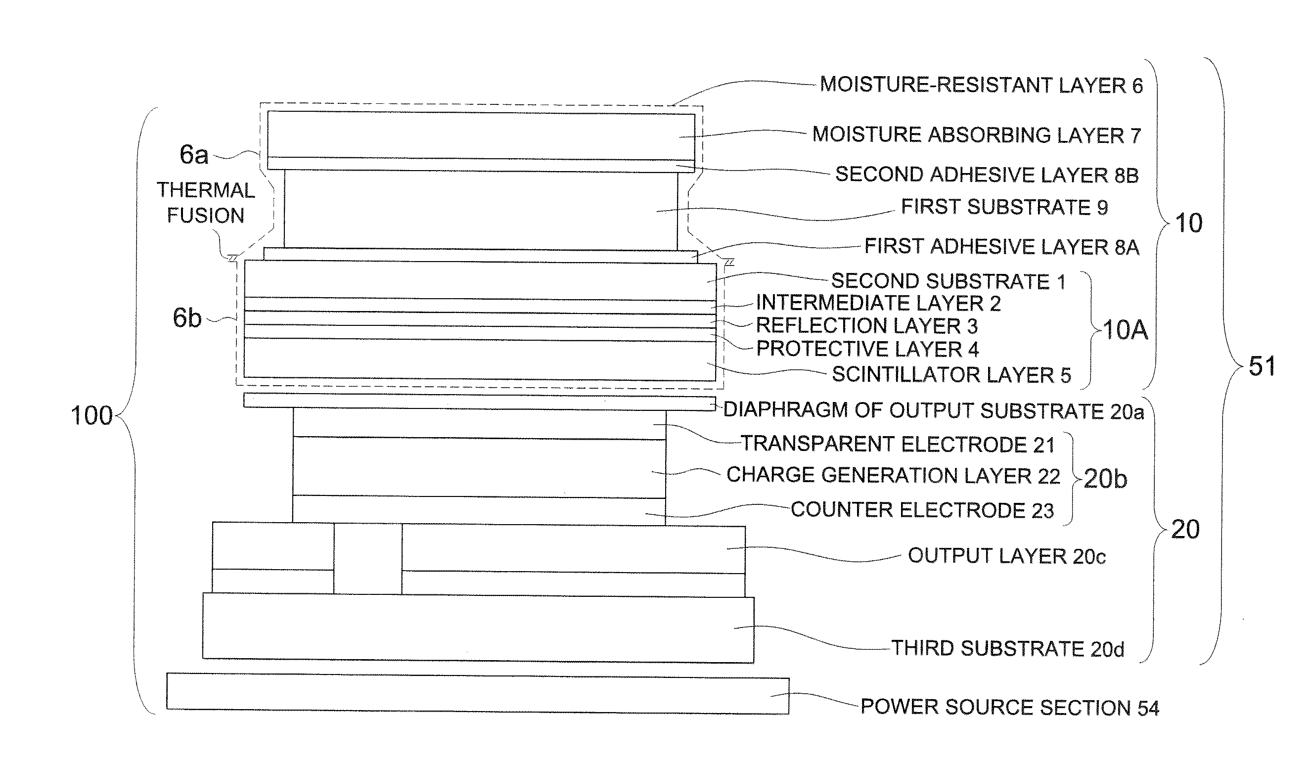
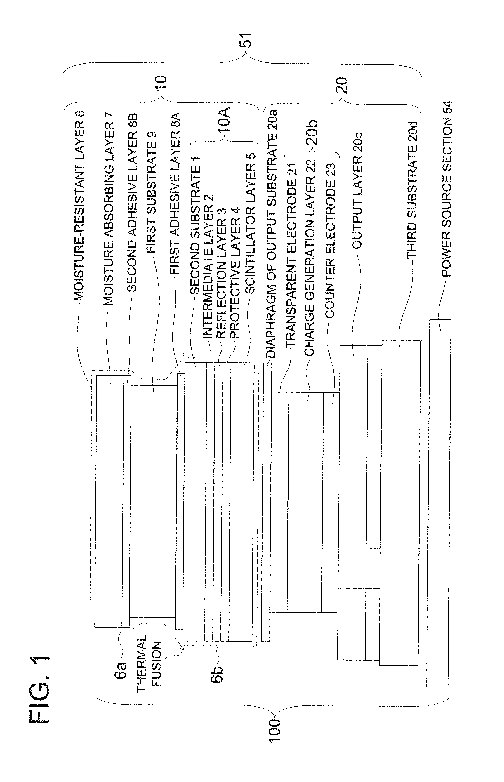
[0177]An adhesion layer of Ni / Cr layer was formed on a 125 μm thick polyimide film (UPILEX-125S, made by Ube Kosan Co., Ltd.), as the second substrate (1), and aluminum was sputtered onto the substrate to form a (0.02 μm thick) reflection layer (3). Thereafter, a (0.08 μm thick) SiO2 layer and a (0.05 μm thick) TiO2 layer were further formed.

Preparation of Protective Layer:

[0178]

Vyron 200 (made by TOYOBO Co., Ltd.,100 parts by masspolyester resin, Tg: 67° C.)Hexamethylene diisocyanates 3 parts by massPhthalocyanine Blue 0.1 part by massMethyl ethyl ketone (MEK)100 parts by massToluene100 parts by mass

[0179]The foregoing composition was mixed and dispersed by a bead mill over 15 hours to obtain a coating solution for a protective layer 4.

[0180]The coating solution was coated by an extrusion coater on the surface of the reflection layer 3 of the second substrate 1 so that the dry thickness was 2.5 μm.

Formation of Scintillator Layer:

[0181]The foregoing s...


PUM


Abstract

A radiation detector of a compact size and producing almost no image defect is disclosed, comprising a first radiation-transmissive substrate, a first adhesive layer, a second radiation-transmissive substrate, a scintillator layer and an output substrate provided with a photoelectric conversion element layer which are provided sequentially in this order, wherein an arrangement region of the scintillator layer in a planar direction of the layer includes an arrangement region of the photoelectric conversion element layer in a planar direction of the layer and an arrangement region of the first substrate in a planar direction of the substrate, and the arrangement region of the first substrate includes the arrangement region of the photoelectric conversion element layer; and when the arrangement region of the scintillator layer is divided to plural areas, a coefficient of variation of filling factor is 20% or less which is defined as a standard deviation of filling factor of phosphor of the plural areas, divided by an average value of the filling factor.

Description

TECHNICAL FIELD[0001]The present invention relates to a radiation detector for use in medical diagnostic apparatuses, nondestructive inspection instruments and the like.TECHNICAL BACKGROUND[0002]There have been broadly employed radiographic images such as X-ray images for diagnosis of the conditions of patients on the wards. Specifically, radiographic images using an intensifying-screen / film system have achieved enhancement of speed and image quality over its long history and are still used on the scene of medical treatment as an imaging system having high reliability and superior cost performance in combination. However, these image data are so-called analog image data, in which free image processing or instantaneous image transfer cannot be realized.[0003]Recently, there appeared digital system radiographic image detection apparatuses, as typified by a computed radiography (also denoted simply as CR) and a flat panel detector (also denoted simply as FPD). In these apparatuses, dig...

Claims


Application Information

Patent Timeline
Patent Type & Authority Applications(United States)
IPC IPC(8): H01L31/115
CPCC09K11/628G21K2004/06G21K4/00G01T1/2018G01T1/20189
Inventor GOTO, NARITOSEKIGUCHI, MITSURU
Owner KONICA MINOLTA MEDICAL & GRAPHICS INC
Why Eureka
Try Eureka