Electrophotographic photoreceptor, production method thereof, and electrophotographic apparatus

a photoreceptor and photoreceptor technology, applied in electrographic processes, instruments, coatings, etc., can solve the problems of insufficient removal of toner from the photoreceptor surface, shorten the life of the photoreceptor, and failure of color balance and reproducibility, so as to improve the mechanical strength of the photosensitive layer, reduce the wear amount of the photoreceptor surface, and improve the effect of the mechanical strength

Active Publication Date: 2021-07-27
FUJI ELECTRIC CO LTD
View PDF19 Cites 0 Cited by
  • Summary
  • Abstract
  • Description
  • Claims
  • Application Information

AI Technical Summary

Benefits of technology

[0026]In order to solve the above-mentioned problems, the present inventors have conducted intensive studies on the materials of the outermost layer of a photoreceptor, and thus provide a photoreceptor having excellent film wear resistance, few image defects, and stable image quality when repeatedly used. Specifically, the present inventors have discovered that a satisfactory electrophotographic photoreceptor can be obtained by applying the following constitution, and thus have completed the present invention.
[0030]In the present invention, a photosensitive layer contains an inorganic oxide, so as to improve the mechanical strength of the photosensitive layer. Moreover, the present inventors have discovered that a high quality photoreceptor can be provided by the use of the inorganic oxide exhibiting extremely high light transmittance when dispersed in a solvent at a high concentration. In this case, the viscosity of the 20% by mass inorganic oxide slurry is preferably 50 mPa·s or less. Further, it is only required that the primary particle diameter of the inorganic oxide maintains a high transmittance when dispersed in a solvent, and preferably ranges from 1 to 500 nm.
[0035]According to the present invention, the use of a photosensitive layer having the above conditions makes it possible to obtain an electrophotographic photoreceptor capable of reducing the wear amount of the photoreceptor surface upon long-term use, causing no filming on the photoreceptor surface, and obtaining stable images. This is because of the following reasons.
[0036]In the present invention, the photosensitive layer contains an inorganic oxide, so as to improve the mechanical strength of the photosensitive layer. However, conventional techniques are disadvantageous in that when the inorganic oxide alone is dispersed in a solvent, aggregated portions are generated, and when dispersion is then performed upon mixing with a charge transport material and a resin component, sufficient dispersion cannot be performed because of increased viscosity due to the addition of the resin component, resulting in a photoreceptor with minute defects on the image. On the other hand, in the present invention, a very high luminous transmittance is exhibited when the inorganic oxide is dispersed at a high concentration with respect to the solvent, indicating the uniform dispersion of the inorganic oxide and the maintenance of the solvation state similarly to that of primary particles. Specifically, in the present invention, even if the inorganic oxide is dispersed in a solvent in a high concentration state, the viscosity of the slurry (dispersion liquid) is low, and as a result, facilitating the mixing with the coating solution in which the constituents of the other photosensitive layer are dissolved. Accordingly, the aggregability at the time of mixing is also reduced, so that a higher-quality photoreceptor can be provided.
[0037]Meanwhile, only the inorganic oxide contained therein can reduce the wear amount of the photoreceptor surface, but leads to an increase in frictional force between a cleaning blade and the photoreceptor surface. Particularly when the inorganic oxide having a particle diameter of 200 nm to 500 nm is contained, the temperature of the photoreceptor surface tends to increase, a silica component that is an external additive contained in a toner becomes softer because of the increased temperature of the photoreceptor surface, tends to adhere to the inorganic oxide, and cannot be cleanly removed easily by a cleaning blade, and thus filming takes place easily on the photoreceptor surface. In the present invention, through the use of a lubricant resin together with the inorganic oxide, frictional force between the cleaning blade and the photoreceptor surface is significantly reduced, the temperature rise of the photoreceptor surface is suppressed, and cleaning performance is improved, so that the problem of filming can also be solved. That both wear resistance and filming resistance can be achieved with the combination of such a specific inorganic oxide and a lubricant resin is the finding obtained for the first time by the studies conducted by the present inventors.

Problems solved by technology

Furthermore, when paper powder and external additives remain on the blade, scratches are made on the surface of an organic photoreceptor and can shorten the life of the photoreceptor.
Therefore, the photoreceptor is increasingly worn, resulting in potential variation, sensitivity variation, and image abnormality, and, in the case of a color machine, resulting in failures in color balance and reproducibility.
Further, if a reverse-polarity toner, which may be mixed in an extremely small amount, is present, there is a problem that such toner cannot be sufficiently removed from the photoreceptor surface, and the charging device is contaminated.
Further, ozone, nitrogen oxides and the like generated upon charging of a photoreceptor may contaminate the photoreceptor surface.
This causes a problem of image deletion due to contaminants themselves, and a problem such that adhered substances lower the lubricity of the photoreceptor surface and facilitate adhesion of paper powder and toners, which causes blade noise, peeling, and formation of scratches on the surface.
However, uniform dispersion of a filler is difficult by such a method that involves dispersing a filler in a film.
Further, the presence of filler aggregates, decreased film transmittance and exposure light scattered by a filler result in non-uniform charge transport and charge generation, and thus image characteristics may deteriorate.
Further, there is a method that involves adding a dispersion material in order to improve filler dispersibility, but in this case, the dispersion material itself adversely affects photoreceptor characteristics, making it difficult to sufficiently achieve both the photoreceptor characteristics and filler dispersibility.
Furthermore, while the addition of a filler improves wear resistance, filming takes place easily on the photoreceptor surface, and handling of image failures is also not taken into consideration.
Further, Patent Documents 3, 4, 5 and 6 propose that a photosensitive layer contains filler particles in order to improve wear resistance, however, photoreceptor characteristics affected by particle aggregation upon preparation of a photosensitive layer coating solution, a production method of particles, effects on impurity control and surface treatment are not sufficiently verified.
Further, Patent Document 7 proposes that in order to obtain a photoreceptor causing less wears upon long-term use and being capable of realizing stable images, a photosensitive layer is formed using an inorganic oxide satisfying predetermined conditions, however, a problem of filming on the photoreceptor surface is not examined.
However, these methods that involve forming a surface protective layer is problematic in that film formation on a charge transport layer is difficult, and achieving both charge transport performance and charge retention function sufficiently is difficult.

Method used


Image

  • Electrophotographic photoreceptor, production method thereof, and electrophotographic apparatus
  • Electrophotographic photoreceptor, production method thereof, and electrophotographic apparatus
  • Electrophotographic photoreceptor, production method thereof, and electrophotographic apparatus

Examples


examples

[0156]Hereinafter, specific embodiments of the present invention will be described in more detail using Examples. The present invention is not limited by the following examples unless it exceeds the gist.

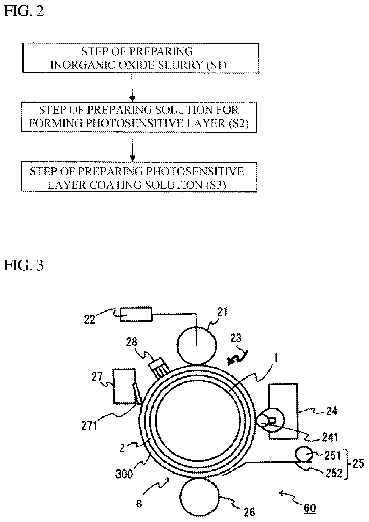
[0157]Preparation of Inorganic Oxide Slurry

production examples 1 to 20

[0158]According to production examples listed in Table 2 below, inorganic oxide slurries were prepared. Specifically, each inorganic oxide slurry was obtained by surface-treating each silica manufactured by Admatechs Company Limited, (YA010C (aluminum element content: 500 ppm), YA050C (aluminum element content: 900 ppm), YA100C (aluminum element content: 900 ppm), YA180C (aluminum element content: 900 ppm), and YA400C (aluminum element content: 900 ppm)) as an inorganic oxide using a treatment agent listed in Table 2 as a surface treatment agent to prepare surface-treated silica, and then dispersing the silica (primary dispersion) in tetrahydrofuran (THF) for a photosensitive layer coating solution. The inorganic oxide after surface treatment in Production Example 1 was subjected to the quantitative determination of the amount of the surface treatment agent, and thus the amount was 0.8% by mass with respect to the inorganic oxide after treatment.

[0159]

TABLE 2Inorganic oxideSurface t...

example 1

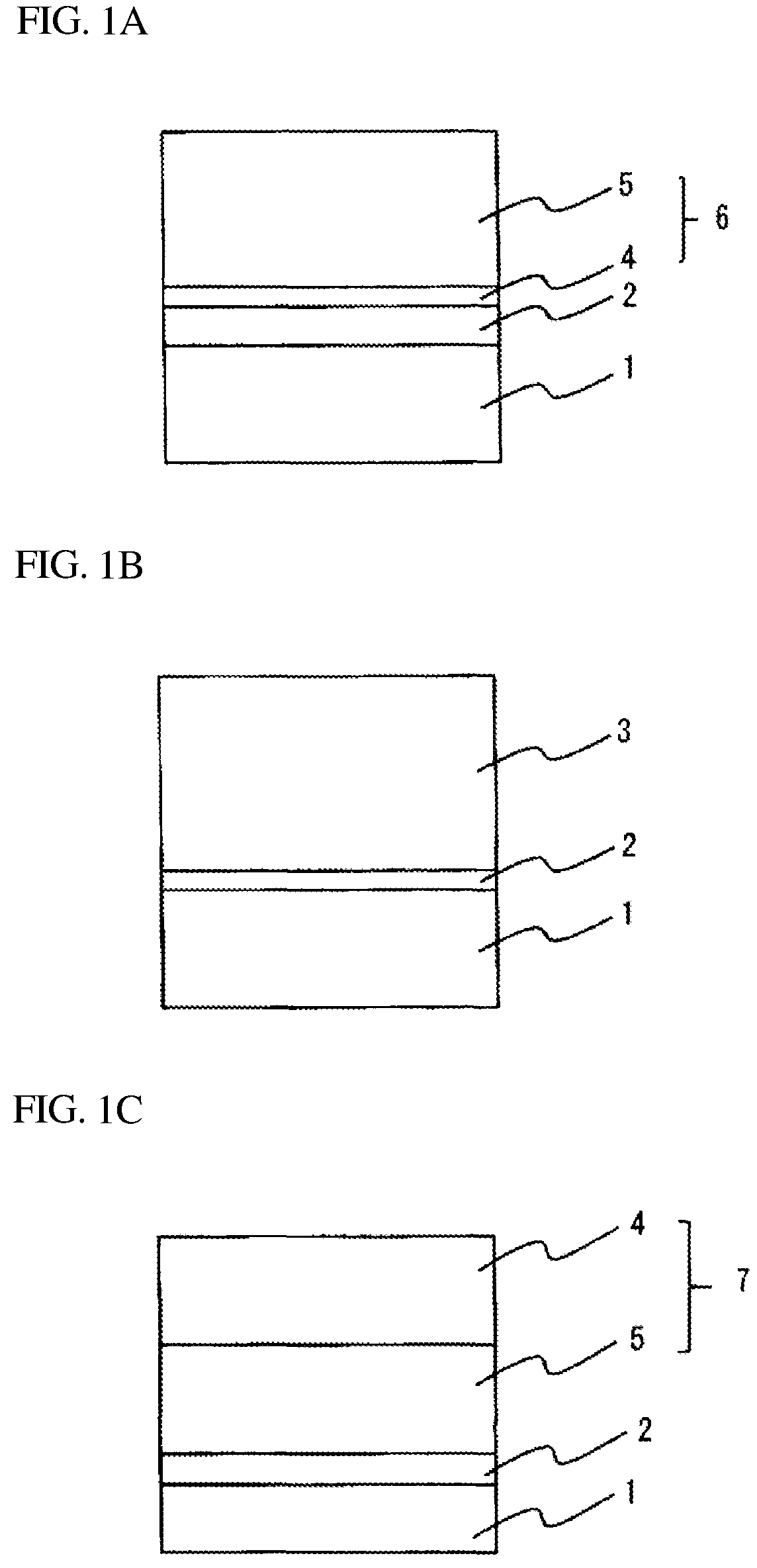
[0161]A coating solution 1 was prepared by dissolving and dispersing 5 parts by mass of alcohol-soluble nylon (trade name “CM8000” manufactured by Toray Industries, Inc.) and 5 parts by mass of aminosilane-treated titanium oxide fine particles in 90 parts by mass of methanol. The outer periphery of an aluminum cylinder having an outer diameter of 30 mm as the electroconductive substrate was dip-coated with the coating liquid 1, and then the resultant was dried at a temperature of 100° C. for 30 minutes, thereby forming an undercoat layer having a thickness of 3 μm.

[0162]One part by mass of Y-type titanyl phthalocyanine as a charge generation material and 1.5 parts by mass of a polyvinyl butyral resin (trade name “ESREC BM-2” manufactured by Sekisui Chemical Co., Ltd.) as a resin binder were dissolved and dispersed in 60 parts by mass of dichloromethane, thereby preparing a coating solution 2. The undercoat layer was dip-coated with the coating solution 2. After 30 minutes of drying ...


PUM

PropertyMeasurementUnit
light transmittanceaaaaaaaaaa
viscosityaaaaaaaaaa
particle diameteraaaaaaaaaa

Abstract

An electrophotographic photoreceptor includes an electroconductive substrate; and a photosensitive layer that is formed on the electroconductive substrate and that contains an inorganic oxide and a lubricant resin which contains a polycarbonate resin having a siloxane structure therein or a polyarylate resin having a siloxane structure therein. When light having a wavelength of 780 nm is irradiated onto a slurry containing 20% by mass of the inorganic oxide in a predetermined solvent to provide an inorganic oxide slurry, the inorganic oxide slurry has a light transmittance that is 80% or more. The photosensitive layer may be a negatively-charged laminate-type photosensitive layer, a monolayer type photosensitive layer, or a positively-charged laminate-type photosensitive layer. The electrophotographic photoreceptor is less worn upon long-term use, allows no filming, and can realize stable images. A method for producing the electrophotographic photoreceptor and an electrophotographic apparatus including the electrophotographic photoreceptor are disclosed.

Description

CROSS-REFERENCE TO RELATED APPLICATION(S)[0001]This non-provisional application for a U.S. patent claims the benefit of priority of JP 2019-050275 filed Mar. 18, 2019, the entire content of which is hereby incorporated by reference.BACKGROUND OF THE INVENTION1. Field of the Invention[0002]The present invention relates to an electrophotographic photoreceptor (hereinafter, also referred to as a “photoreceptor”), a production method thereof, and an electrophotographic apparatus. Specifically, the present invention relates to an electrophotographic photoreceptor which is mainly composed of a photosensitive layer including an electroconductive substrate and an organic material, and is used for an electrophotographic printer, a copying machine, a fax machine, etc., a production method thereof, and an electrophotographic apparatus.2. Background of the Related Art[0003]An electrophotographic photoreceptor has a basic structure in which a photosensitive layer having a photoconductive functio...

Claims


Application Information

Patent Timeline
Patent Type & Authority Patents(United States)
IPC IPC(8): G03G5/00G03G5/047G03G5/05G03G5/087G03G15/00
CPCG03G5/047G03G5/056G03G5/0525G03G5/0564G03G5/0589G03G5/0592G03G5/087G03G15/75G03G5/05G03G5/0578G03G2215/00957
Inventor ZHU, FENGQIANGHASEGAWA, TOMOKISUZUKI, SHINJIROTAKEUCHI, MASARU
Owner FUJI ELECTRIC CO LTD
Why Eureka
Try Eureka