Construction vehicle

a construction vehicle and vehicle body technology, applied in the field of construction vehicles, can solve the problems of increasing the cost of vehicle maintenance, tire exchange frequency, and reducing the efficiency of working, so as to prevent overshooting and improve the accuracy

Inactive Publication Date: 2012-01-05
KOMATSU LTD
View PDF16 Cites 11 Cited by
  • Summary
  • Abstract
  • Description
  • Claims
  • Application Information

AI Technical Summary

Benefits of technology

[0018]In a preferred embodiment of the present invention, said controller may further comprise a degree of engagement increase unit (176) that, if the result of said operational state determination is affirmative but the result of said drive force determination is negative (NO in S21), increases said degree of engagement (S33) on the basis of a build-up value at a lower speed than said build-down value. Due to this, if the actual drive force has dropped to lower than the set drive force, then it is possible to return the actual drive force to the set drive fore. In this case, since the build-up value is smaller than the build-down value, it is possible effectively to prevent overshoot in which the actual drive force exceeds the set drive force for a second time. Said build-up value is stored in the memory of the controller.
[0019]In a preferred embodiment of the present invention: said construction vehicle may be a wheel loader; said travel device may comprise a transmission; said task of a predetermined type may include excavation; and said controller may perform said operational state determination by making decisions as to whether or not the speed stage of said transmission is a predetermined forward speed stage, whether or not the tilt angle of said construction vehicle is less than a predetermined angle, whether or not said construction vehicle is moving forwards or is stopped, and whether or not, the state of said work equipment is a predetermined state during excavation. By making the decisions in this wheel loader on the basis of a plurality of conditions of these types, it is possible to detect with good accuracy an excavation task for which there may be a problem of the actual drive force exceeding the set drive force.

Problems solved by technology

With a construction vehicle such as, for example, a wheel loader or the like, when performing a task such as excavation that requires a large travel drive force, if the travel drive force being outputted from the travel drive wheels (i.e. the travel propulsion force) is excessively great in view of the state of the road surface, slippage between the tires and the road surface, destruction of a fragile road surface, or the like may occur, and this leads to a decrease in the efficiency of working.
Moreover, tire slippage is accompanied by early wear and tear upon the tires, and this leads to the tire exchange frequency becoming high and to increase of the cost of vehicle maintenance.

Method used


Image

  • Construction vehicle
  • Construction vehicle
  • Construction vehicle

Examples


Embodiment Construction

[0028]In the following, an embodiment of the present invention will be explained with reference to the drawings by citing a case of application thereof to a wheel loader, as an example of a construction vehicle. However, this embodiment could also be applied to a construction vehicle other than a wheel loader.

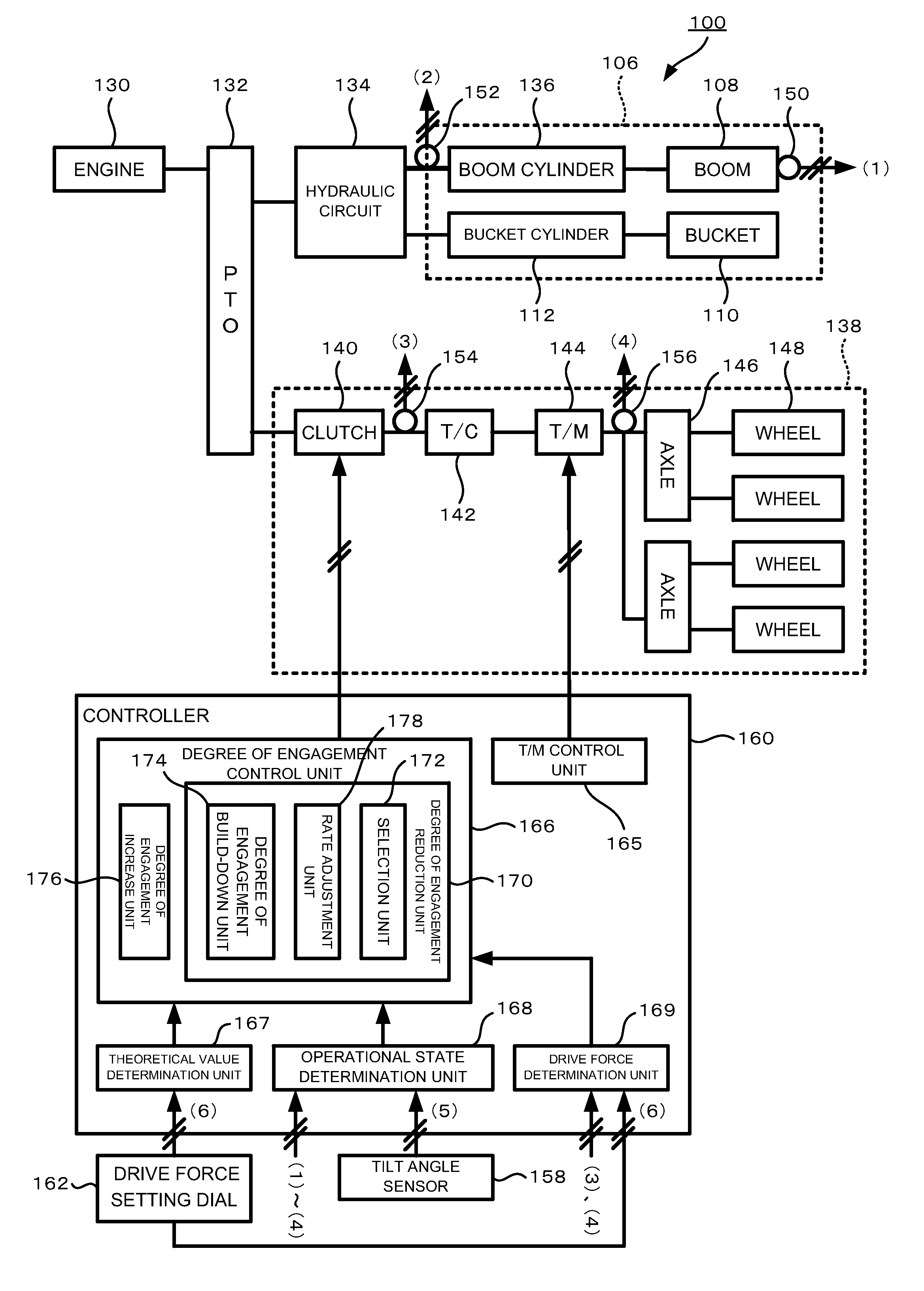
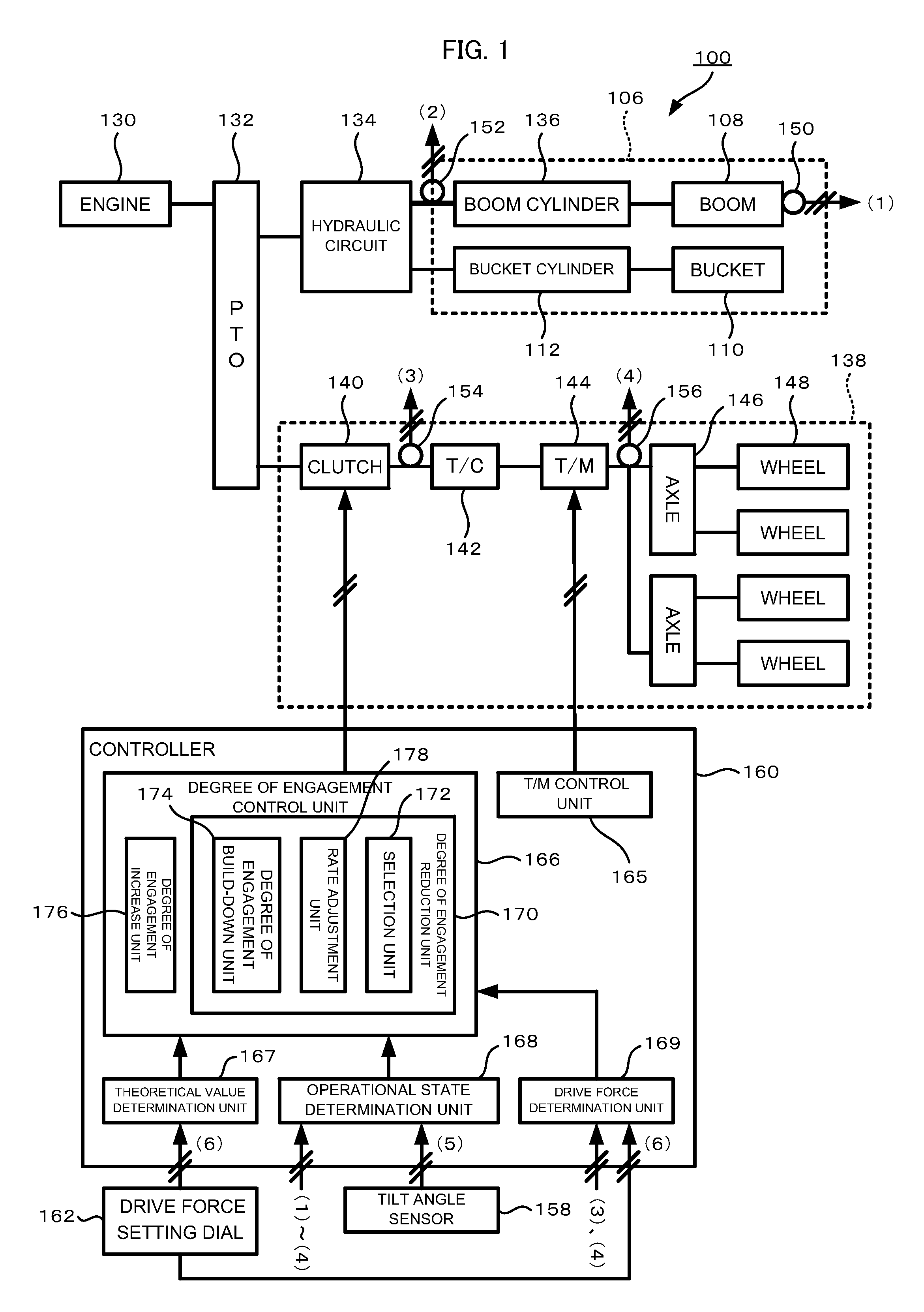
[0029]FIG. 1 is a block diagram schematically showing the overall structure of a wheel loader 100 according to this embodiment.

[0030]Principally, this wheel loader 100 comprises an engine 130, a travel device 138, a work equipment 106, a hydraulic circuit 134, an output splitter (PTO: Power Take Off) 132 that divides the output of the engine 130 between the travel device 138 and the hydraulic circuit 134, and a controller 160.

[0031]The travel device 138 is a device for causing the wheel loader 100 to travel. This travel device 138, for example, comprises a clutch 140, a torque converter (T / C) 142, a transmission (T / M) 144, axles 146, and wheels 148. The power outputted from the...


PUM


Abstract

The construction vehicle is provided with an engine, a clutch, a travel device, a work equipment, a drive force setting dial, and a controller that includes: a theoretical value determination unit that determines a theoretical value, for the degree of engagement to make the upper limit value of the drive force equal to a set drive force; an operational state determination unit that determines whether the work equipment is outputting the drive force in a predetermined travel direction; a drive force determination unit that determines whether the drive force is greater than the set drive force; and a degree of engagement reduction unit that, if of operational state determination and of drive force determination are both affirmative, causes the degree of engagement to approach the theoretical value.

Description

TECHNICAL FIELD[0001]The present invention relates to a construction vehicle, and in particular relates to a technique for control of the travel drive force.BACKGROUND ART[0002]With a construction vehicle such as, for example, a wheel loader or the like, when performing a task such as excavation that requires a large travel drive force, if the travel drive force being outputted from the travel drive wheels (i.e. the travel propulsion force) is excessively great in view of the state of the road surface, slippage between the tires and the road surface, destruction of a fragile road surface, or the like may occur, and this leads to a decrease in the efficiency of working. Moreover, tire slippage is accompanied by early wear and tear upon the tires, and this leads to the tire exchange frequency becoming high and to increase of the cost of vehicle maintenance.[0003]If, in order to solve this problem, the driver observes the state of the road surface and sets the travel drive force by a m...

Claims


Application Information

Patent Timeline
Patent Type & Authority Applications(United States)
IPC IPC(8): E02F9/20G06F19/00E02F3/36
CPCE02F9/2025E02F9/202E02F9/2253
Inventor TOCHIZAWA, MAMORUTAKAHASHI, KOJISAITO, YOSHIAKI
Owner KOMATSU LTD
Why Eureka
Try Eureka