[0032]In one embodiment of the
vibration damper of the invention, the damping part comprises, at least on a front side thereof, an axially elastic damping
washer. As a result of the arrangement of the elastic damping part radially between the two shaft parts with an
axial length for transmitting torque, it is possible to dispense with flanges, which have a radial
diameter that is many times the shaft
diameter and between which the elastic damping part is disposed. Since the axial extension of a shaft is given anyway in most applications and therefore not relevant to the installation space, it is possible to save installation space in the radial direction by using the proposed vibration
damper of the invention which only marginally expands the shaft
diameter. As a result of the improved guidance of the two shaft parts relative to each other, flexing is avoided so that there is reduced development of heat, and therefore higher efficiency is achieved. The vibration damper also has the
advantage, for example, that it makes do with less installation space.
[0033]A high degree of synchronous operation and balancing quality is achieved by means of the so-called tube-in-tube arrangement of the shaft parts with the damping part. The parts are self-centering on each other so that it is possible to dispense with a centering operation when mounting the shaft parts on each other.
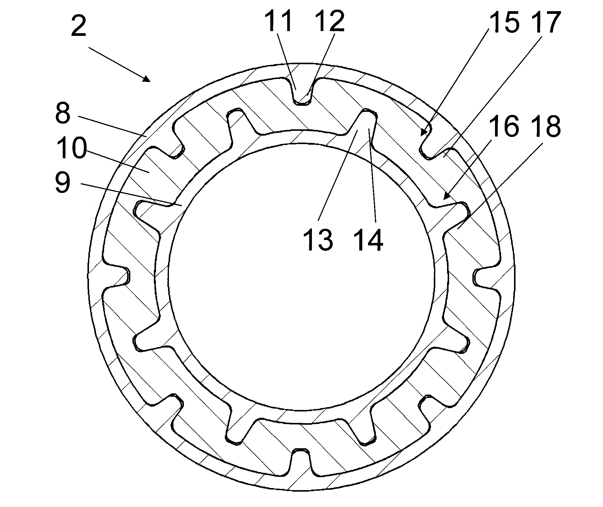
[0037]By using variably elastic materials, there preferably results a
surface pressure between the rotary drivers and the harder material on the one hand and a
surface pressure between the harder material and the more elastic material on the other. The surface ratios between the rotary drivers and the negative profiles are configured to be appropriately smaller than the surface ratios of the different materials of the damping part so that a lesser
surface pressure is achieved on the elastic material by means of the selection and arrangement of the different materials, while higher surface pressure and therefore smaller contact surfaces can be achieved by the use of a more rigid material for
torque transmission from the shaft parts into the damping part.
[0040]The combination of the vibration damper with a
constant velocity joint has proved particularly advantageous. In this case, the
constant velocity joint is mounted on the first or the second shaft part, for example, so as to be rotationally fixed in that it is mounted on the damper in a rotationally fixed manner, for example, by means of corresponding profiling, for example, on the rotary drivers already provided for acting upon the damping part, and is fixed axially, for example, crimped against an axial stop. In doing so, it can be advantageous if the preferably lubricated
constant velocity joint is encapsulated relative to the damping part. Among other things, a sealing
washer can be disposed between the
constant velocity joint and the damping part in this connection. Advantageously, the sealing
washer can also be made of a base part of the sleeve so that there is no requirement of any additional parts. The use of a
constant velocity joint in the vibration damper enables large articulation angles to be maintained permanently in the shaft without damage to the damping part. Furthermore, a very good synchronous operation is achieved even at larger articulation angles. Similarly, it is possible to provide not only fixed ball joints but also constant velocity joints comprising slip joints and / or displacement units in the form of roller compensators.
[0041]According to a further advantageous illustrative embodiment, the vibration damper can additionally exhibit an axial damping effect in that the damping part is fixed or braced axially between the two shaft parts. In this case, the damping part may comprise axially elastic portions. These portions can be provided, in sandwich architecture, on one or both end faces and / or in between in that the damping part is divided into two or more sections or appropriately elastic regions are provided in the same. Alternatively or additionally, the damping part can be provided, on its end faces or in between, with one or more axially elastic damping washers that are acted upon in the case of axial loads by corresponding axial end faces of the shaft parts. The axial damping travel can be limited in that the shaft parts collide with each other in order to protect the axially elastically effective regions of the damping part from damage in the case of extreme stresses.
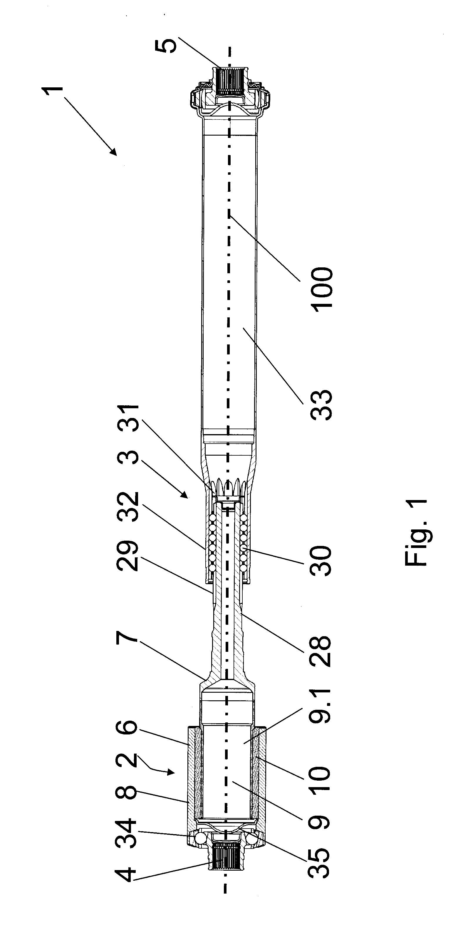
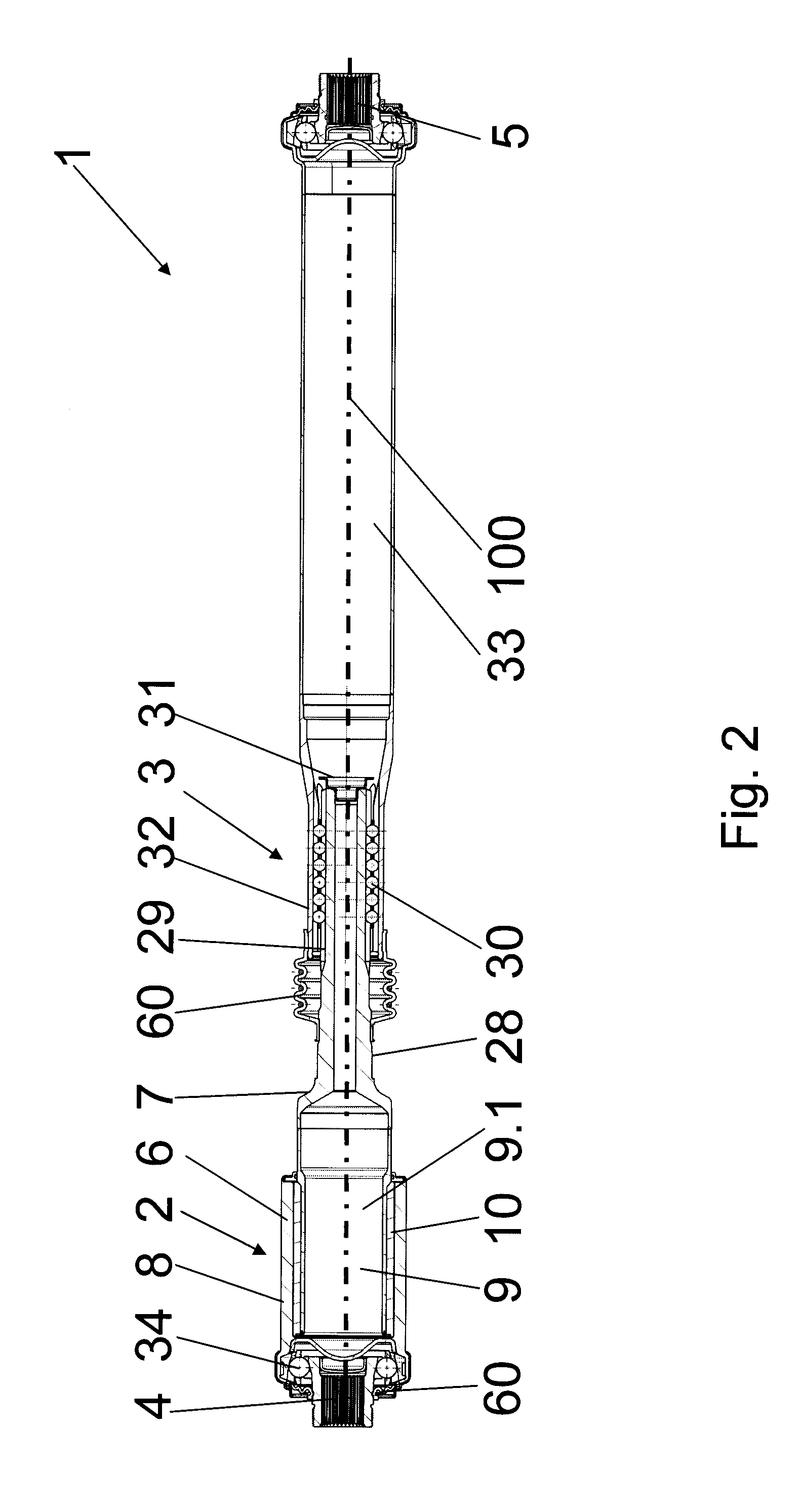
[0042]The invention also relates to a
drive shaft that can be used in the form of a
propeller shaft and / or a side shaft, for example, in a drive
train of a motor vehicle, the
drive shaft comprising rotationally locked end regions for achieving a rotationally locked connection of the drive shaft to additional connecting pieces of the drive
train such as transmission output shafts, differential input or output shafts, wheel hubs and the like, and the vibration damper described above being disposed between the same. Within the scope of the invention, it is possible to provide an
axial length compensation of the drive shaft at a distance from the vibration damper in the axial direction, which length compensation is in the form of, for example, a displacement unit comprising inner teeth disposed on a shaft section, an additional shaft section comprising outer teeth, and rolling elements disposed radially between the same. In one embodiment, a component of the displacement unit forms a
structural unit with the vibration damper. In particular, the vibration damper in an additional embodiment comprises longitudinal teeth for the
axial length compensation. In doing so, it has proved advantageous if the displacement unit or at least a component of the same is provided in the form of a
structural unit with the vibration damper in that, for example, the outer teeth or preferably the inner teeth are provided on a shaft part of the vibration damper so that the number of shaft components can be reduced, for example, to three and the number of interruptions in the shaft can be minimized in favor of achieving a stability of the shaft.

