
Adaptive event-guided system and method for avoiding voltage emergencies

Inactive Publication Date: 2012-01-05
PRESIDENT & FELLOWS OF HARVARD COLLEGE
View PDF13 Cites 52 Cited by
  • Summary
  • Abstract
  • Description
  • Claims
  • Application Information

AI Technical Summary

Benefits of technology

[0018]A voltage emergency predictor anticipates voltage emergencies using “voltage emergency signatures” and throttles machine execution to prevent them. An emergency signature is an interleaved sequence of control-flow events and microarchitectural events leading up to an emergency. A voltage emergency signature is captured when an emergency first occurs by taking a snapshot of relevant event history and storing it in the predictor. A built-in checkpoint-recovery mechanism then rolls the machine back to a known correct state and resumes execution. Subsequent occurrences of the same emergency signature cause the predictor to throttle execution and prevent the impending emergency. By doing so, the predictor enables aggressive timing margins in order to maximize performance.
[0020]In contrast, the present invention recognizes and tracks patterns of emergency-prone activity to proactively throttle execution well before an emergency can occur. The experimental results show high prediction accuracy is possible, which translates to performance enhancements by reducing otherwise conservative margins.
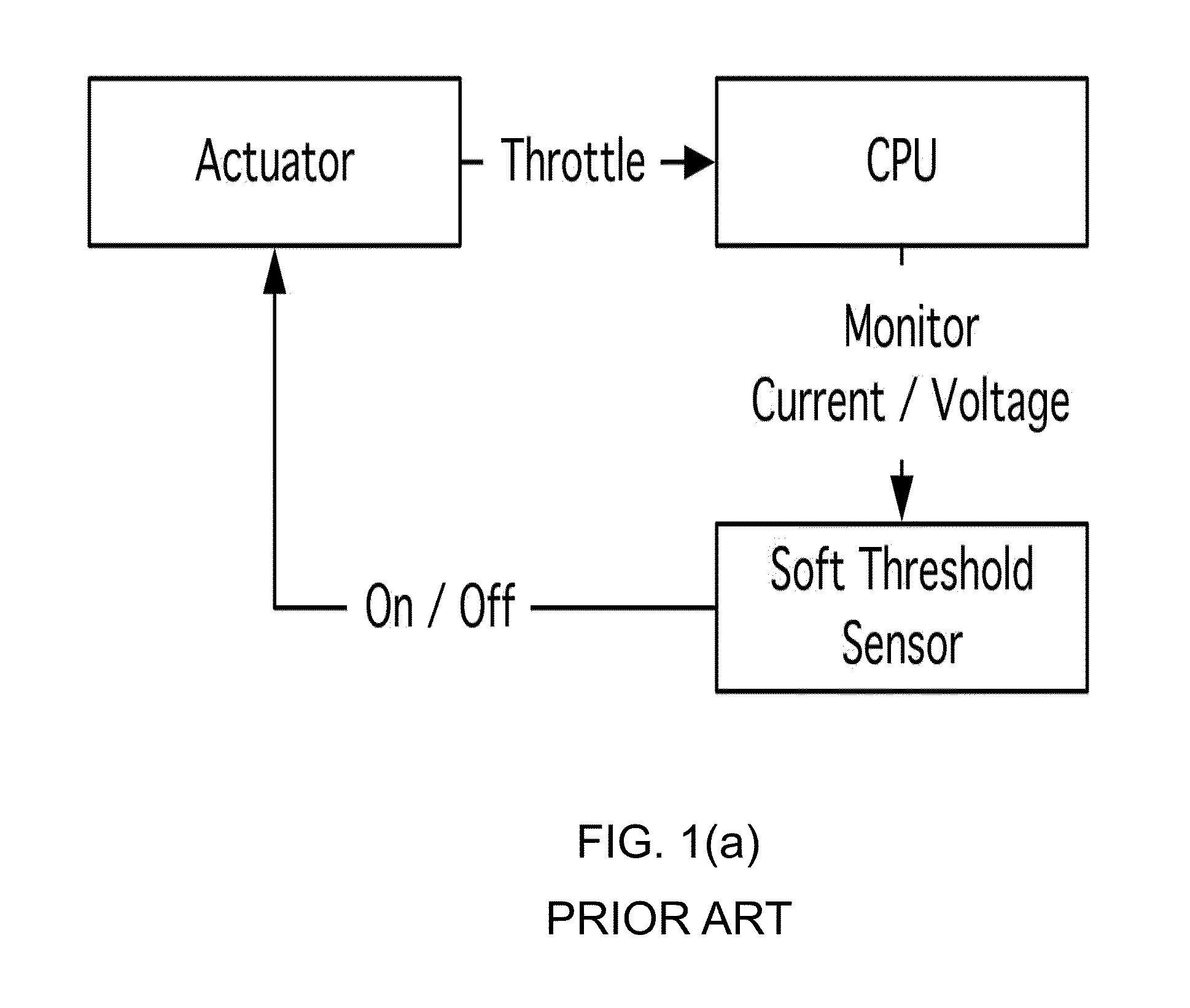
[0021]An additional benefit is that the voltage emergency predictor of the present invention does not require fine tuning based on specifics of the microarchitecture nor the power delivery subsystem, as is the case with reactive sensor-based schemes. The current and voltage activity of a microprocessor are products of machine utilization that are specific to the workload's dynamic demands. Capturing that activity in the form of voltage emergency signatures allows the predictor to dynamically adapt to the emergency-prone behavior patterns resulting from the processor's interactions with the power delivery subsystem without having to be preconfigured to reflect the characteristics of either.

Problems solved by technology

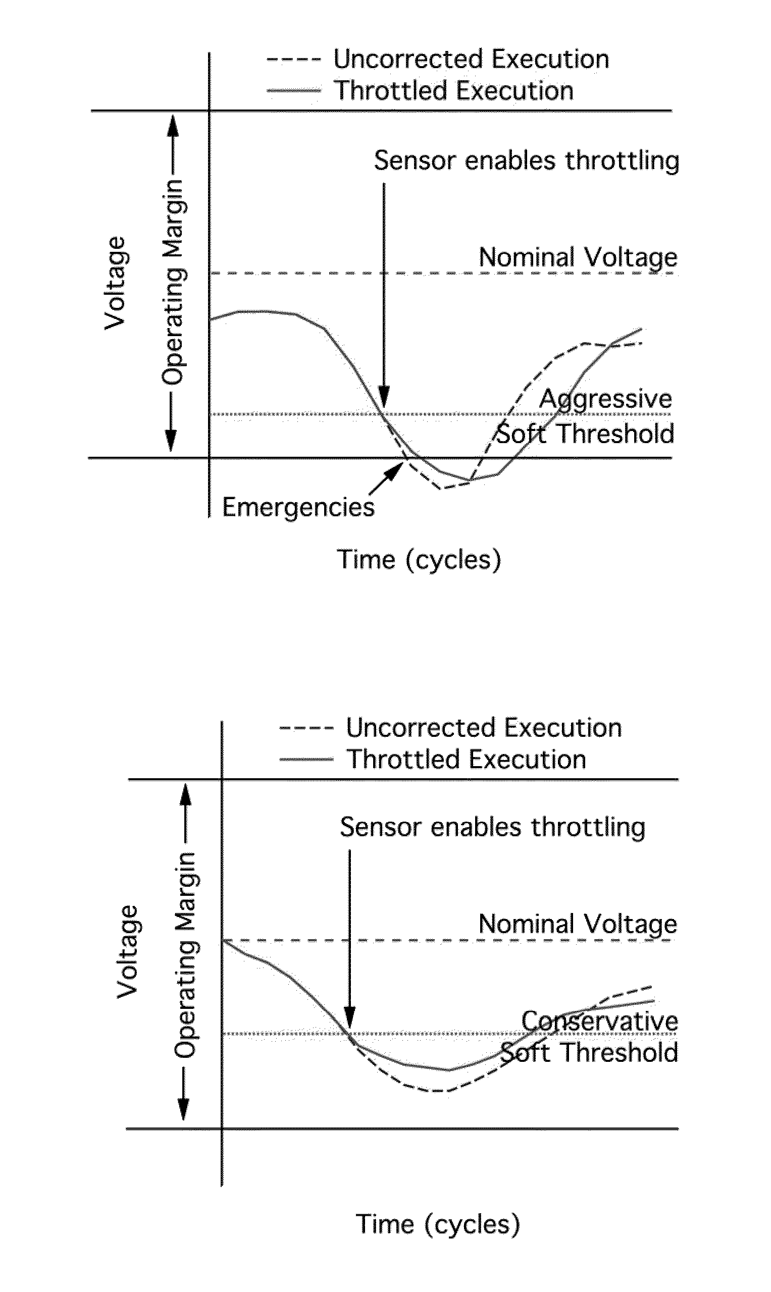
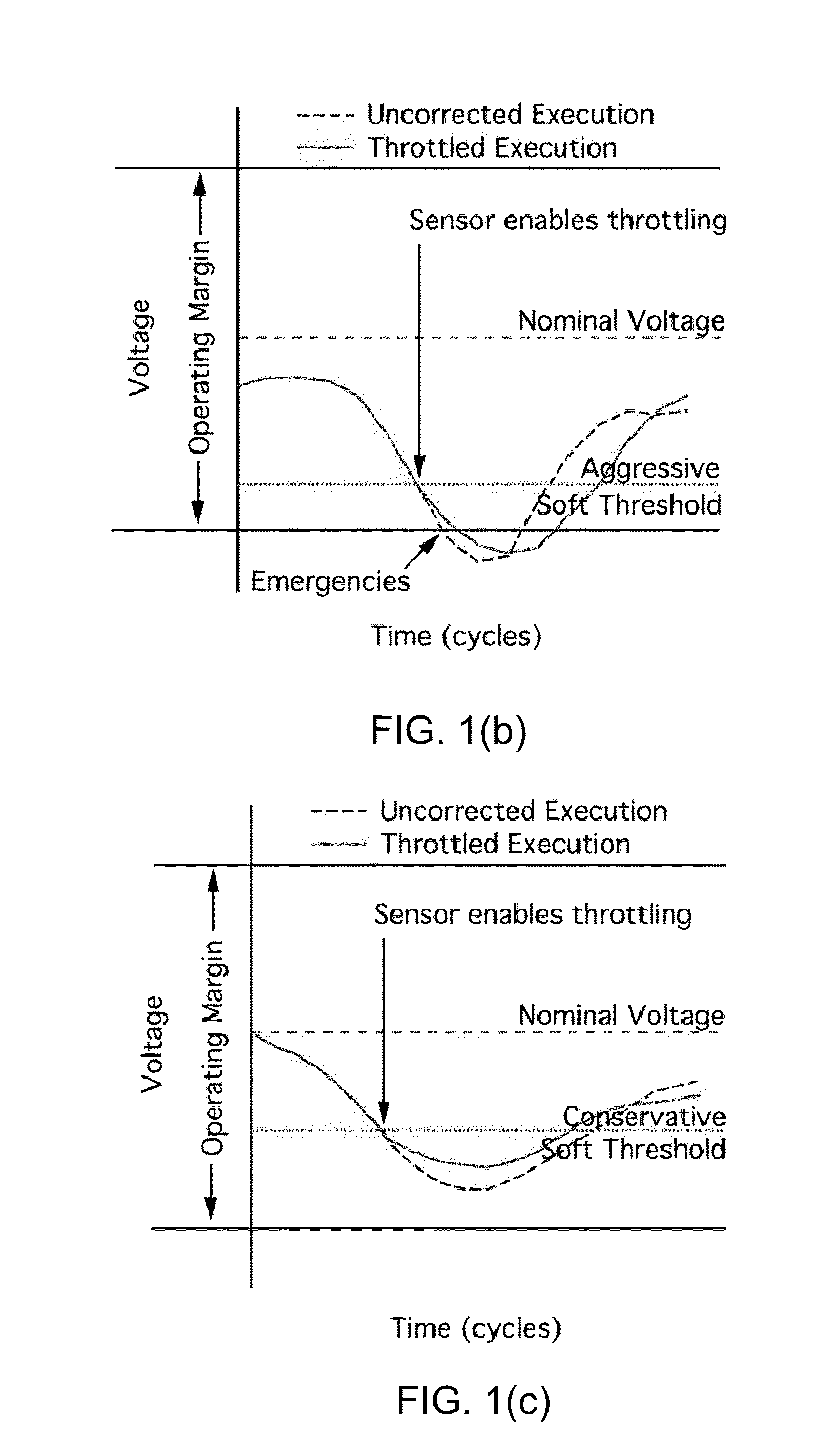
Unfortunately, these schemes cannot always guarantee correctness without incurring large performance penalties.
Alternatively, setting the threshold too conservatively leads to unnecessary throttling that degrades performance.

Method used


Image

  • Adaptive event-guided system and method for avoiding voltage emergencies
  • Adaptive event-guided system and method for avoiding voltage emergencies
  • Adaptive event-guided system and method for avoiding voltage emergencies

Examples


examples

[0090]The vehicle for the examples presented below is the x86 SimpleScalar infrastructure. Table 1 lists the configuration parameters used to initialize SimpleScalar for our baseline microprocessor design, which we refer to as Arch 1.

TABLE 1Baseline architecture (Arch 1) parameters for SimpleScalar.Clock Rate3.0 GHzInst. Window128-ROB, 64-LSQFunctional Units8 Int ALU, 4 FP ALU,2 Int Mul / Div, 2 FP Mul / DivFetch Width8 InstructionsL1 D-Cache64 KB 2-wayL2 I / D-Cache2 MB 4-way, 16 cycle latencyRAS64 EntriesBranch Penalty10 cyclesBranch Predictor BTB64-KB bimodal gshare / chooser 1K EntriesDecode Width8 InstructionsL1 I-Cache64 KB 2-wayMain Memory300 cycle latency

[0091]The workload set is comprised of benchmarks from the SPEC CPU2006 suite. All but a few were simulated for 100 million instructions across their different inputs using the phase most heavily weighted by Simpoint (1445.gobmk input 13x13, 456.hmmer, 471.omnetpp, 473.astar, 434.zeusmp, 453.povray and 470.lbm are omitted because Si...


PUM


Abstract

In a preferred embodiment, the present invention is a system for avoiding voltage emergencies. The system comprises a microprocessor, an actuator for throttling the microprocessor, a voltage emergency detector and a voltage emergency predictor. The voltage emergency detector may comprise, for example, a checkpoint recovery mechanism or a sensor. The voltage emergency predictor of a preferred embodiment comprises means for tracking control flow instructions and microarchitectural events, means for storing voltage emergency signatures that cause voltage emergencies, means for comparing current control flow and microarchitectural events with stored voltage emergency signatures to predict voltage emergencies, and means for actuating said actuator to throttle said microprocessor to avoid predicted voltage emergencies.

Description

CROSS-REFERENCE TO RELATED APPLICATIONS[0001]The present application claims the benefit of the filing date of U.S. Provisional Patent Application Ser. No. 61 / 151,936 filed by the present inventors on Feb. 12, 2009.[0002]The aforementioned provisional patent application is hereby incorporated by reference in its entirety.STATEMENT REGARDING FEDERALLY SPONSORED RESEARCH OR DEVELOPMENT[0003]This invention was made with government support under CCF-0429782 and CSR-0720566 awarded by the National Science Foundation. The government has certain rights in the invention.BACKGROUND OF THE INVENTION[0004]1. Field of the Invention[0005]The present invention relates to systems and methods for predicting current swings that can cause the voltage in a microprocessor to fluctuate beyond safe levels and for avoiding such swings.[0006]2. Brief Description of the Related Art[0007]Power-constrained CMOS designs are making it increasingly difficult for microprocessor designers to cope with power supply ...

Claims


Application Information

Patent Timeline
IPC IPC(8): G06F11/30
CPCG06F1/28
Inventor REDDI, VIJAY JANAPAGUPTA, MEETA SHARMAHOLLOWAY, GLENNWEI, GU-YEONSMITH, MICHAEL D.BROOKS, DAVID
Owner PRESIDENT & FELLOWS OF HARVARD COLLEGE
Features
  • Generate Ideas
  • Intellectual Property
  • Life Sciences
  • Materials
  • Tech Scout
  • Unparalleled Data Quality
  • Higher Quality Content
  • 60% Fewer Hallucinations
Learn More