
Flange Plate, Flange Connection and Exhaust Manifold

a technology of flange connection and exhaust manifold, which is applied in the field of flange plates, can solve problems such as thermal expansion effects, and achieve the effects of significantly reducing the danger of critical stresses and reducing the danger of buckling formation due to thermal expansion effects

Active Publication Date: 2012-01-12
PUREM GMBH
View PDF9 Cites 0 Cited by
  • Summary
  • Abstract
  • Description
  • Claims
  • Application Information

AI Technical Summary

Benefits of technology

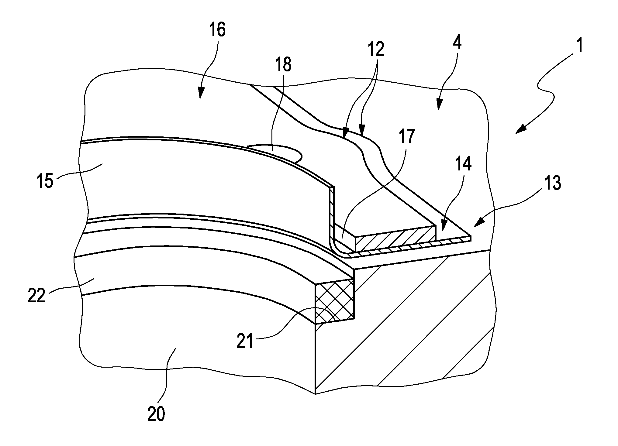
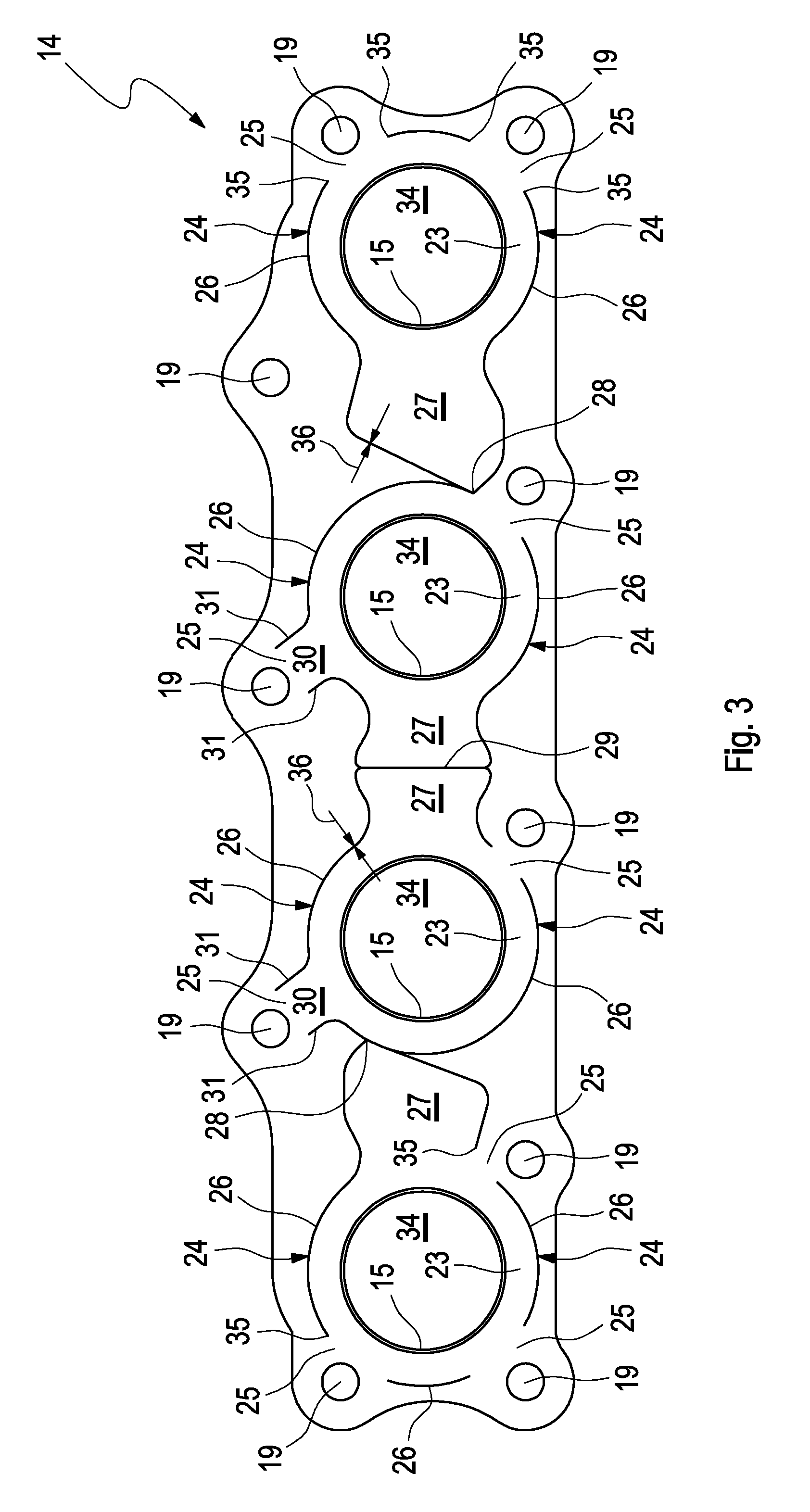
[0005]The invention is based on the general idea of providing a flange plate having at least two connecting sockets integrally moulded out of the flange plate on each of which an exhaust pipe can be fastened and which has a plurality of through openings provided for fixing the flange plate to the combustion engine, e.g. suitable for the passing through of screws with at least one connecting region which comprises at least one of the connecting sockets and which is surrounded by a slit penetrating the flange plate. In order for said connecting region to remain connected to the flange plate despite the slit, the respective slit comprises at least one interruption in the region of which the respective connecting region remains connected to the remaining flange plate while it is separated from the flange plate in the remainder, that is along the slit. This design results in that the connecting region with the respective connecting socket can move relative to the remaining flange plate. Because of this, thermally induced expansions can be elastically absorbed as a result of which the danger of critical stresses can be reduced. The invention in this case is based on the consideration that the connecting sockets reach higher temperatures than the flange plate connected to the combustion engine. With the help of the respective slit the respective connecting region containing the respective connecting socket is cut free from the remaining connecting plate except for the respective interruption and separated, so that the connecting sockets with the exhaust pipes fastened thereon can move relative to the remaining connecting plate and thus relative to the combustion engine. Furthermore, especially in the region of the connecting sockets or in the connecting regions the danger of a buckling formation due to thermal expansion effects is significantly reduced.
[0006]According to a preferred embodiment the respective slit runs within the flange plate separately and at a distance from socket openings, wherein each socket opening is enclosed by one of the connecting sockets and is penetrating the flange plate. In other words, the respective slit runs out or outwith of the connecting sockets or out or outwith of the socket openings, respectively. Thus, for example, leakage can be avoided or reduced which may occur in case the respective slit would run into such a socket opening or would fluidically connect two of such socket openings with each other.
[0007]Additionally or alternatively can be provided that the respective slit runs within the flange plate separately and at a distance from the through openings, i.e. the respective slit runs within the flange plate out or outwith the through openings. Thus, for example, detrimental interaction with the fixation of the flange plate can be avoided or reduced.

Problems solved by technology

It is problematic there that in operation of the combustion engine high temperatures develop on the exhaust gas side, which result in thermal expansion effects.
In particular, these stresses can result in buckling formation in the region of the common flange, so that leakages develop there through which the exhaust gas can escape into the environment untreated.

Method used


Image

  • Flange Plate, Flange Connection and Exhaust Manifold
  • Flange Plate, Flange Connection and Exhaust Manifold
  • Flange Plate, Flange Connection and Exhaust Manifold

Examples


Embodiment Construction

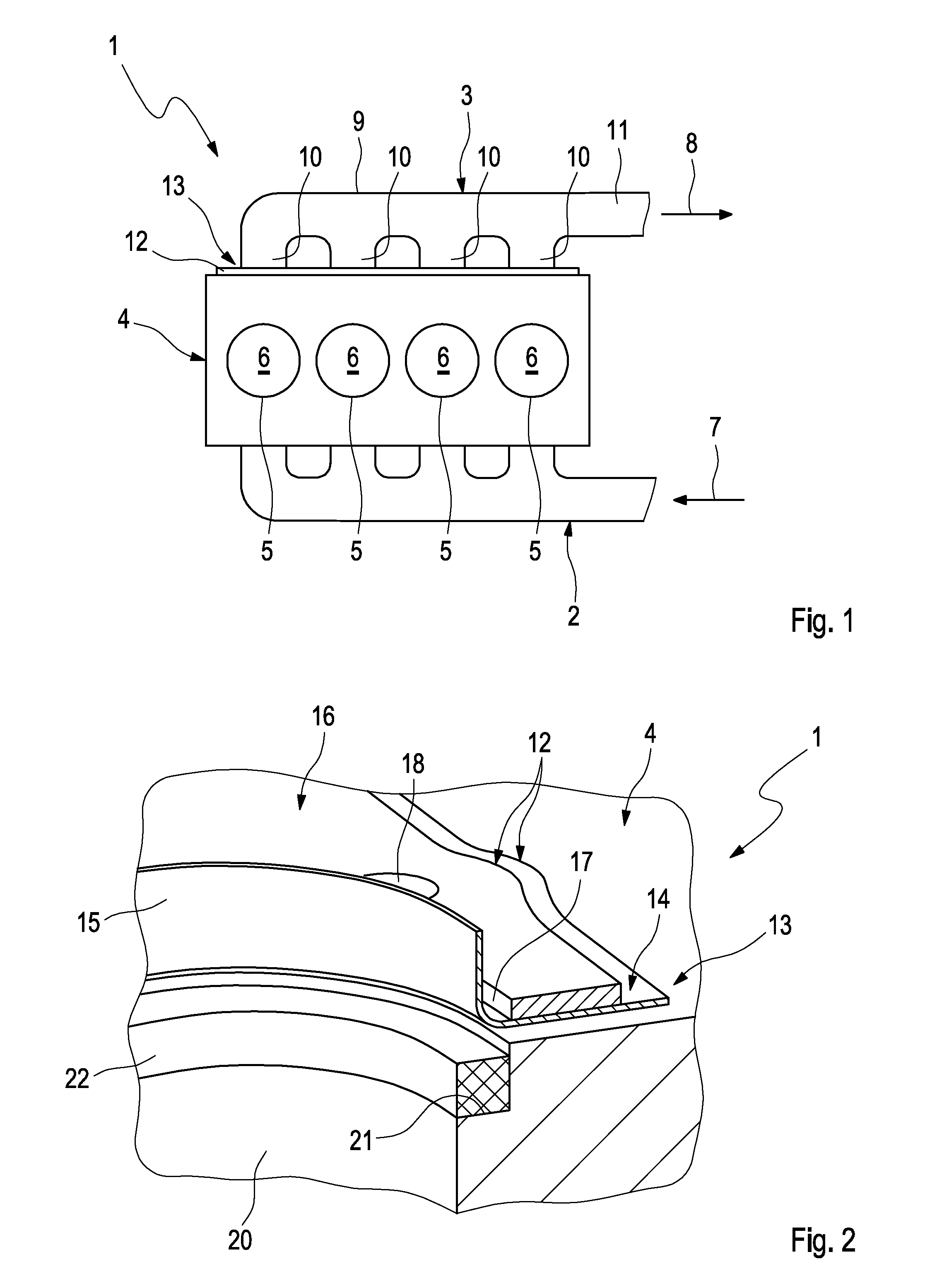
[0030]According to FIG. 1, a combustion engine 1 can be equipped in the usual manner with a fresh air system 2 and with an exhaust system 3. In the example, the combustion engine 1 comprises an engine block 4 containing a plurality of cylinders 5, each of which surrounding a combustion chamber 6. Instead of an individual cylinder block 4 the combustion engine 1 can also comprise two cylinder banks, for example in the case of a V-engine.

[0031]The fresh air system 2 serves for feeding fresh air 7 to the cylinders 5 or to the combustion chambers 6. To this end, the fresh air system 2 on the outlet side is fastened to the engine block 4.

[0032]The exhaust system 3 serves for discharging exhaust gas 8 from the cylinders 5 or from the combustion chambers 6. To this end, the exhaust system 3 is fastened to the engine block 4 on the inlet side. The exhaust system 3 on the inlet side comprises an exhaust manifold 9 having an exhaust pipe 10 for each cylinder 5 and is connected to the remainin...


PUM


Abstract

The present invention relates to a flange plate for connecting exhaust pipes to a combustion engine, with at least two connecting sockets integrally moulded on the flange plate, on each of which an exhaust pipe can be fastened, and with a plurality of through openings for fixing the flange plate to the combustion engine.Thermal expansion effects can be better compensated if at least one of the connecting sockets is formed in a connecting region, which is surrounded by a slit penetrating the flange plate, wherein the respective slit comprises at least one interruption and the respective connecting region in the region of the respective interruption is connected to the remaining flange plate.

Description

CROSS-REFERENCE TO RELATED PATENT APPLICATIONS[0001]This patent application claims the benefit of German Patent Application No. 10 2010 026958.1, filed Jul. 12, 2010, the entire teachings and disclosure of which are incorporated herein by reference thereto.FIELD OF THE INVENTION[0002]The present invention relates to a flange plate for connecting exhaust pipes to a combustion engine. The invention additionally relates to a flange connection for fastening an exhaust system to a combustion engine. Furthermore, the present invention relates to an exhaust manifold for discharging exhaust gas from a combustion engine, particularly of a motor vehicle.BACKGROUND OF THE INVENTION[0003]An exhaust system is usually fastened at the inlet side to a combustion engine in order to be able to discharge the combustion exhaust gases that accrue during the operation of the combustion engine. The inlet region of the exhaust system fastened to an engine block or to a cylinder bank of the combustion engin...

Claims


Application Information

Patent Timeline
IPC IPC(8): F01N13/10F16L39/00
CPCF01N13/08F01N2450/22F01N13/1816F01N13/10
Inventor RIEKERS, RALFHETTEL, ANGELA
Owner PUREM GMBH
Learn More