Dipping Apparatus

a technology of dipping apparatus and dipping rod, which is applied in the direction of lighting and heating apparatus, charging manipulation, furniture, etc., can solve the problems of high cost of positioning and fixing devices, high equipment cost, etc., and achieve the effect of shortening the required front-back direction length, high cost, and considerable equipment cos

Active Publication Date: 2012-01-12
DAIFUKU CO LTD
View PDF0 Cites 20 Cited by
  • Summary
  • Abstract
  • Description
  • Claims
  • Application Information

AI Technical Summary

Benefits of technology

[0004]In the conventional dipping apparatus as described in the above Japanese Patent No. 3638283, the treatment bath is arranged below the traveling path of the conveying traveling body (pallet) along the path. The conveying traveling body is made to move onto the rotation base in the waiting posture from the rear end of the rotation base and positioned and fixed. In this state, the rotation base is rotated. The workpiece is turned upside down together with the conveying traveling body and dipped in the treatment bath. The rotation base is returned to the waiting posture, and then the conveying traveling body is moved forward and advanced onto the ground traveling path from the front end of the rotation base.
[0005]In such a dipping apparatus, the conveying traveling body is made to pass and travel with respect to the treatment bath, as described in Japanese Patent No. 3638283 as well, when the rotation base, positioned immediately below the center of an entire length of the workpiece (vehicle body), is rotated about a horizontal spindle arranged near the front end thereof to shorten a required front-back direction length for the treatment bath. The rotation base while rotating largely projects forward with respect to the horizontal spindle. As a result, measures such that the ground traveling path connected to the front end of the rotation base, more specifically, guide rails and roller conveyors are allowed to escape laterally during rotation of the rotation base are required so that the ground traveling path connected to the front end of the rotation base does not interfere with the rotation base. This leads to considerable equipment costs. Further, a positioning and fixing device to fix the conveying traveling body (pallet) to a fixed position on the rotation base is essential. In the configuration where the conveying traveling body passes through as described above, however, the positioning and fixing device needs to switch the conveying traveling body having moved from the rear side from a state of being positionally fixed with respect to the back and forth direction to a state of being capable of advancing forward. A fixed stopper simply receiving the conveying traveling body at a fixed position cannot be used. Accordingly, the costs become high regarding the positioning and fixing device, too.

Problems solved by technology

This leads to considerable equipment costs.
Accordingly, the costs become high regarding the positioning and fixing device, too.

Method used


Image

  • Dipping Apparatus
  • Dipping Apparatus
  • Dipping Apparatus

Examples


Embodiment Construction

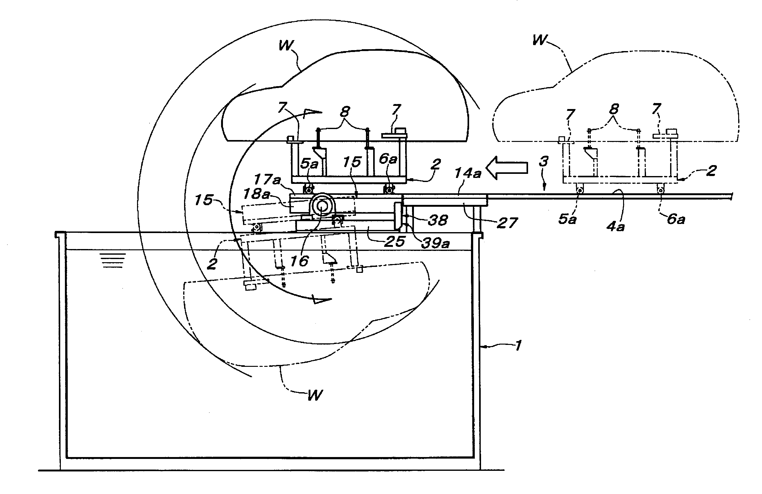
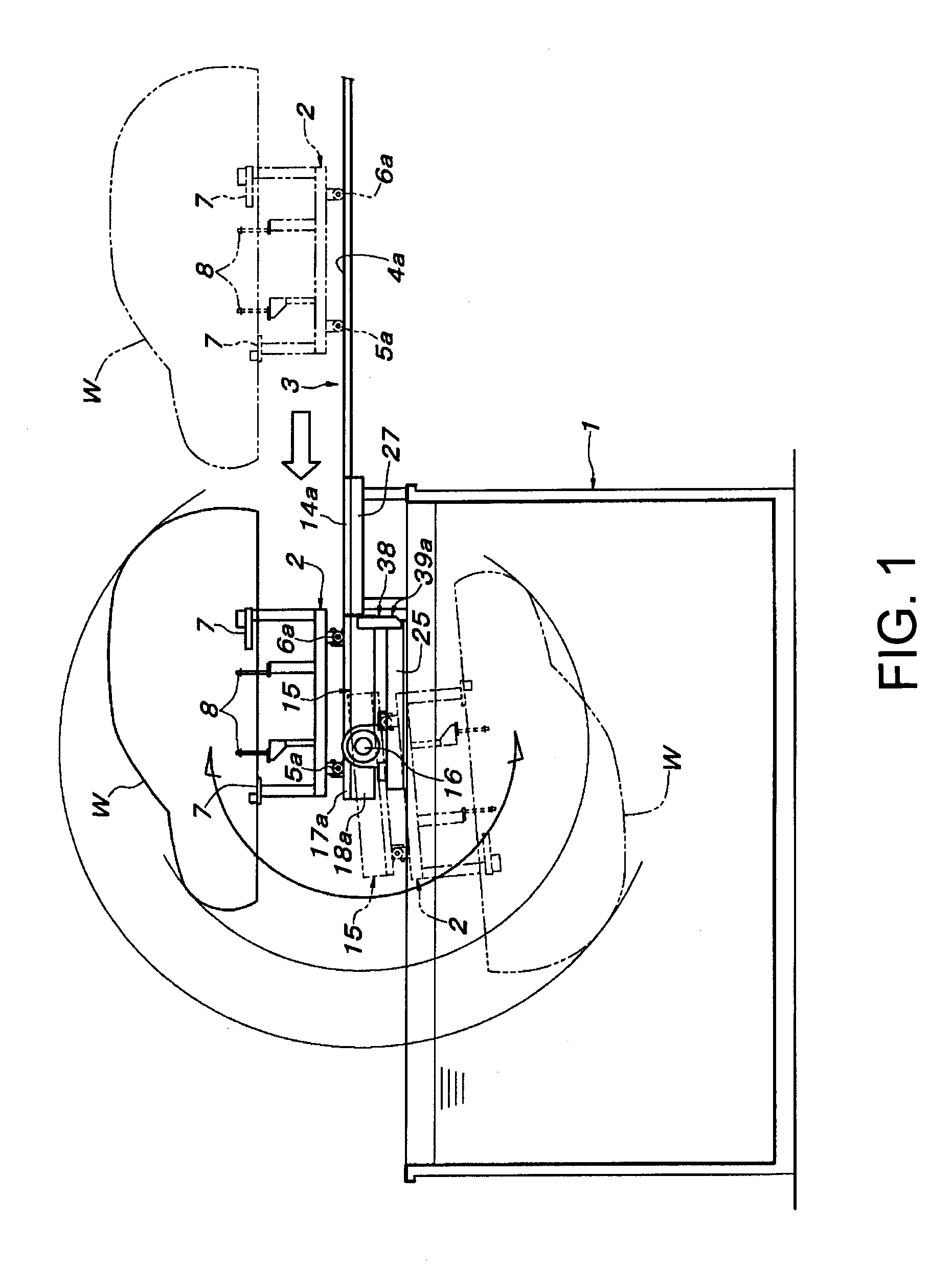
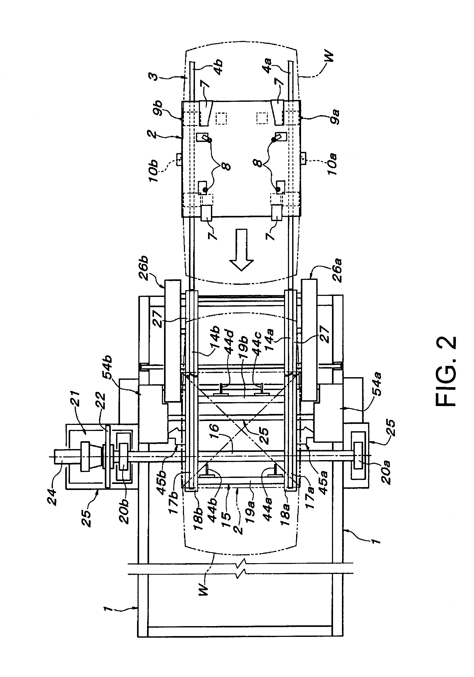
[0039]In FIG. 1 and FIG. 2, reference symbol 1 denotes a treatment bath with a rectangular shape in a plan view and is placed at the end of a ground traveling path 3 of a conveying traveling body 2 in such a direction that longer sides thereof are in parallel with the traveling path 3. The ground traveling path 3 of the conveying traveling body 2 is composed of a pair of left and right guide rails 4a and 4b, and the conveying traveling body 2 includes a pair of front and rear flangeless wheels 5a and 6a rolling on one of the guide rails 4a and a pair of front and rear flanged wheels 5b and 6b rolling on the other guide rail 4b and provided with flanges sandwiching the guide rail 4b, as shown in FIGS. 3 to 5. The conveying traveling body 2 has an upper surface provided with a plurality of workpiece supports 7 to support a workpiece (vehicle body) W and a plurality of workpiece fixtures 8 to fix the workpiece W to the conveying traveling body 2. The conveying traveling body 2 has both...


PUM


Abstract

A dipping apparatus for dipping the workpiece W in a treatment bath. The workpiece is transferred while fixed on a conveying traveling body 2, and each one flipped upside down together into the treatment bath for carrying out a surface treatment of the workpiece W.
The dipping apparatus is provided with a positioning and fixing device to position the conveying traveling body 2 onto the guide rail 17a on the rotation base 15 at a fixed position and to fix the conveying traveling body 2 to the rotation base 15. A feeding mechanism feeds the conveying traveling body 2 to the fixed position on the rotation base 15.

Description

CROSS REFERENCE TO RELATED APPLICATION [0001]This utility patent application claims the priority of JP 2010-155439 filed on Jul. 8, 2010, entitled “Dipping Apparatus,” the entire disclosure of the application being considered part of the disclosure of this application and hereby incorporated by reference.TECHNICAL FIELD [0002]The present invention relates to a dipping apparatus for flipping a workpiece having been conveyed while fixed on a conveying traveling body, upside down together with the conveying traveling body, dipping the workpiece in a treatment bath, and carrying out a surface treatment of the workpiece.BACKGROUND OF THE INVENTION [0003]This kind of dipping apparatus is known as a dipping apparatus for carrying out a surface treatment of a vehicle body of an automobile. More specifically, this kind of dipping apparatus includes a treatment bath into which a workpiece is dipped to treat a surface thereof, a horizontal spindle crossing above the treatment bath, a rotation ...

Claims


Application Information

Patent Timeline
Patent Type & Authority Applications(United States)
IPC IPC(8): B05C3/02
CPCB65G49/0481B05C3/10
Inventor NISHIHARA, SHIGEYOSHIFUKUDA, TAKASHITAKEICHI, HIROHITOFUJISAKI, HIROFUMI
Owner DAIFUKU CO LTD
Why Eureka
Try Eureka