Compact and modular robotic wash system

Active Publication Date: 2012-01-12
ABB INC
View PDF2 Cites 26 Cited by
  • Summary
  • Abstract
  • Description
  • Claims
  • Application Information

AI Technical Summary

Benefits of technology

[0005]In accordance with the present invention, a robotic wash system is provided for cleaning a work piece. The robotic wash system includes a wash booth having a floor, a top wall and one or more side walls. The wash booth defines an interior wash chamber having a maximum horizontal linear dimension. A pre-rinse chamber and a drying chamber are removably connected to the wash booth. A robot is fully disposed inside the wash chamber of the wash booth. The robot includes a base mounted to the floor and a gripper for grasping the work piece. The robot has a maximum horizontal reach that is at least 40% of the maximum

Problems solved by technology

These solvents and the increased mist and humidity from the heat can damage the components and joints of the robotic device.
Moreover, heated working fluids also increase the rate at which biological contaminants grow in the robotic wash system.
These biological contaminants can pose a health hazard to the people working in the plant, and can damage the robotic device and other components in the wash system.
Solvents also make it difficult to recycle the working fluid.
These emulsions are difficult to filter out or separate from the water without using expensive and bulky filtration system.
The oil emulsions adhere to

Method used


Image

  • Compact and modular robotic wash system
  • Compact and modular robotic wash system
  • Compact and modular robotic wash system

Examples


first embodiment

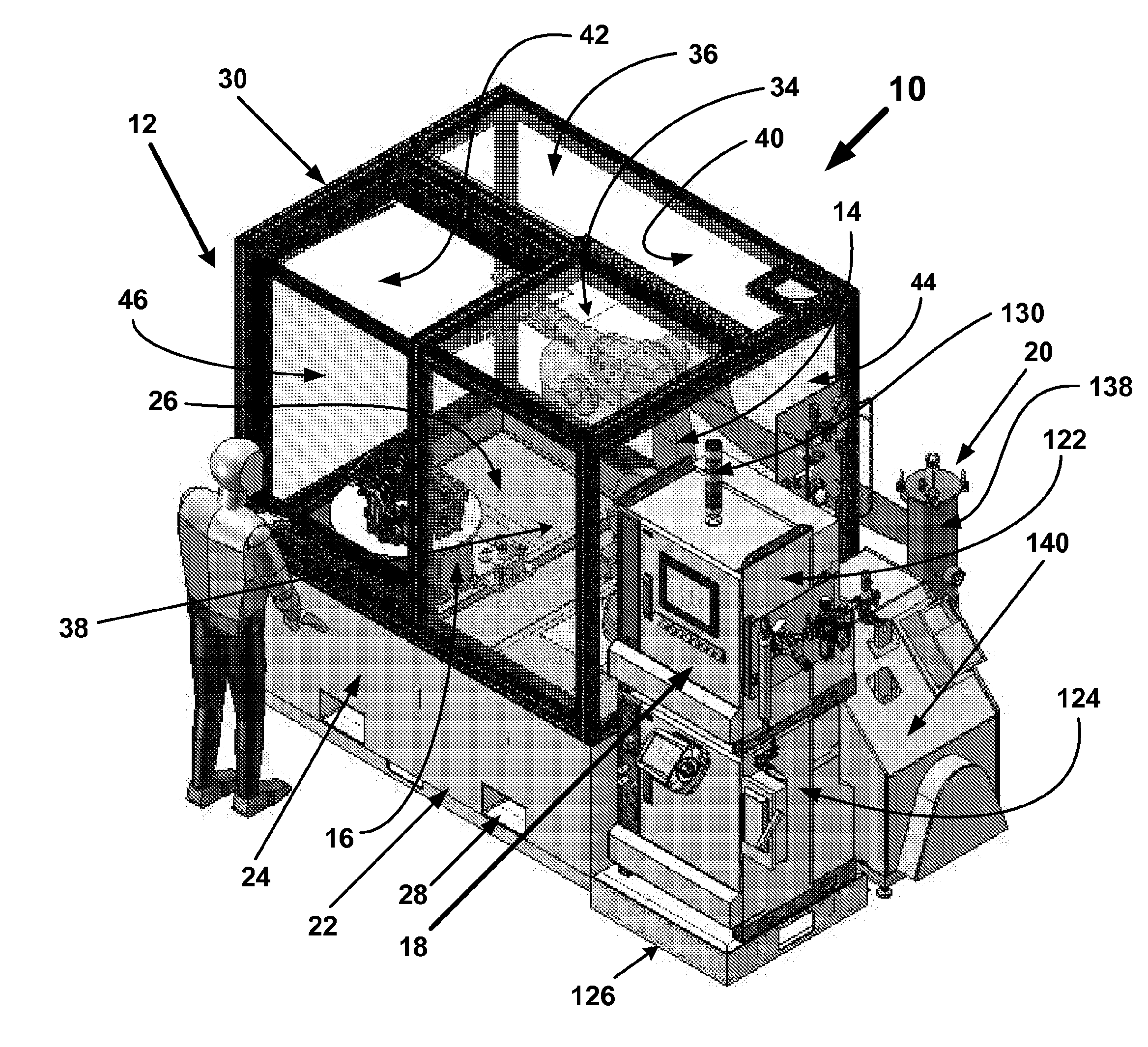
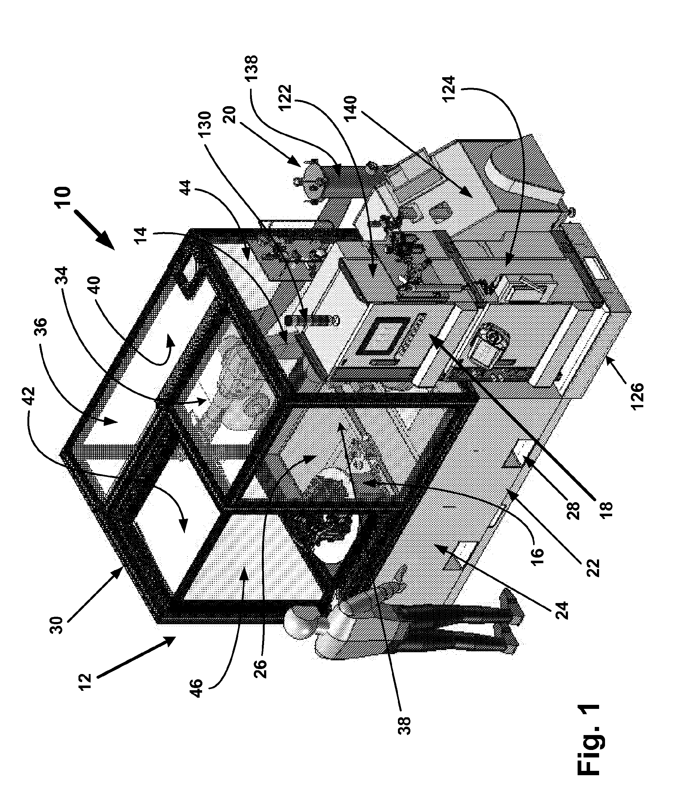
[0020]Referring now to FIG. 1, there is shown a first washer unit 10 constructed in accordance with the present invention. The first washer unit 10 has a compact construction and a small footprint, which is well suited for applications where only limited space is available. The first washer unit 10 generally includes a booth 12, a robot 14, a holding stand 16, a control system 18 and a fluid filtration system 20. The robot 14 and the holding stand 16 are disposed inside the booth 12.

[0021]The booth 12 includes a base structure 22 having a pair of opposing side walls 24 and a pair of opposing end walls, which help support a floor 26. Each side wall 24 has a pair of fork lift pockets 28 adapted for receiving the tines of a fork lift, respectively. At least a portion of the floor 26 disposed around the holding stand 16 is grated and has a multitude of openings to permit water to flow therethrough. The side walls 24, the end walls and the floor 26 cooperate to define a lower access spac...

second embodiment

[0045]Referring now to FIG. 8, there is shown a second washer unit 200 constructed in accordance with the present invention. The second washer unit 200 is larger than the first washer unit 10, but also has a compact construction and a relatively small footprint. The second washer unit 200 generally includes a main booth 202, a robot 204, a control system 18, a fluid filtration system 206 and optionally a pre-rinse chamber 208 and a drying chamber 210. The robot 204 is disposed inside the main booth 202.

[0046]The booth 202 includes a rectangular top enclosure 210 secured to a bottom base structure 212 that encloses an interior sump for receiving water passing through a floor 214 of the base structure 212. The enclosure 210 cooperates with the floor 214 to define an interior wash chamber. The enclosure 210 includes a top panel 216, opposing side panels 218 and first and second end panels 222, 224, each of which may be constructed from sheet metal, such as stainless steel. First and se...


PUM


Abstract

A compact robotic wash system is provided for cleaning a work piece. The robotic wash system includes an enclosed wash chamber. A robot is fully disposed inside the wash chamber. The robot has a maximum horizontal reach that is at least 40% of the maximum horizontal linear dimension of the wash chamber. The robot may hold a work piece and move the work piece around a plurality of spray devices. Alternately, the robot may hold one or more spray devices, while a work piece is supported on a movable table.

Description

BACKGROUND OF THE INVENTION[0001]A conventional robotic wash system includes a variety of components, such as a robotic device and corresponding control system, a working fluid for washing work pieces, a pump to pressurize the fluid, nozzles to spray the fluid at the objects and an end effector or frame to support the nozzles.[0002]Conventional wash systems add solvents and heat to help break down oil or grease that may be present on the work pieces. These solvents and the increased mist and humidity from the heat can damage the components and joints of the robotic device. Moreover, heated working fluids also increase the rate at which biological contaminants grow in the robotic wash system. These biological contaminants can pose a health hazard to the people working in the plant, and can damage the robotic device and other components in the wash system. Solvents also make it difficult to recycle the working fluid. Solvents tend to mix or otherwise combine with the water and oil or ...

Claims


Application Information

Patent Timeline
IPC IPC(8): B08B3/02B08B5/00B08B13/00
CPCB08B3/022B08B13/00B08B3/024F16D1/02
Inventor MILOJEVIC, DRAGOSLAVCARMACK, KENNETH A.RAETZ, DANIEL A.GAUCI, ERICVIGNEAU, JAMES R.BLANCHARD, LARRY X.CAZAN, PAUL G.CAZAN, LOREN J.LASKI, STEPHEN J.
Owner ABB INC
Why Eureka
Try Eureka