
Water jet sweeper

a water jet and sweeper technology, applied in the direction of spraying apparatus, movable spraying apparatus, spray nozzle, etc., can solve the problems of difficult and tiring task of controlling this force, limited functionally to very small directional changes, and large area sweeping task, etc., to achieve easy sweeping task, easy to use, and easy to use

Inactive Publication Date: 2012-01-12
CARR DOUGLAS
View PDF4 Cites 4 Cited by
  • Summary
  • Abstract
  • Description
  • Claims
  • Application Information

AI Technical Summary

Benefits of technology

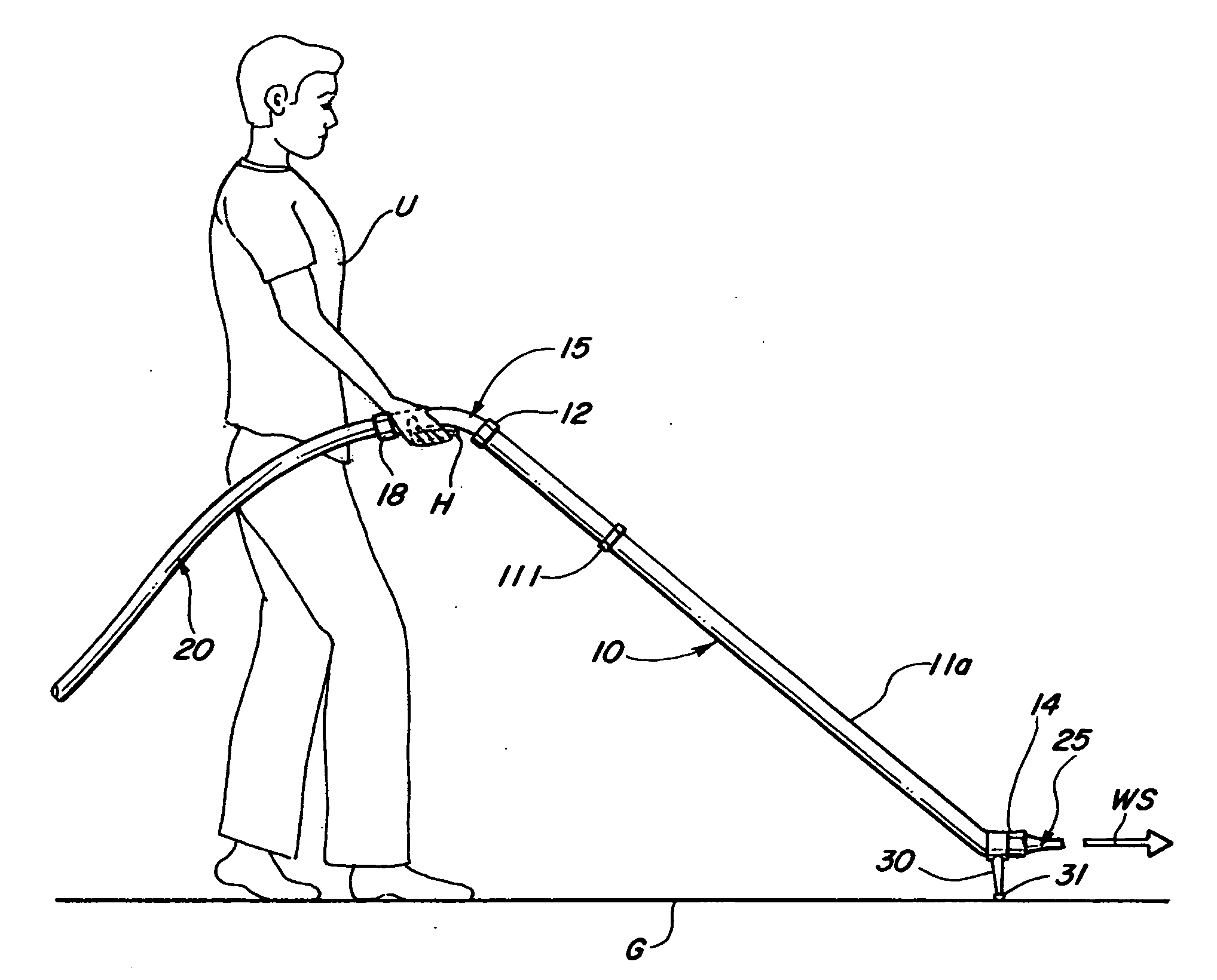
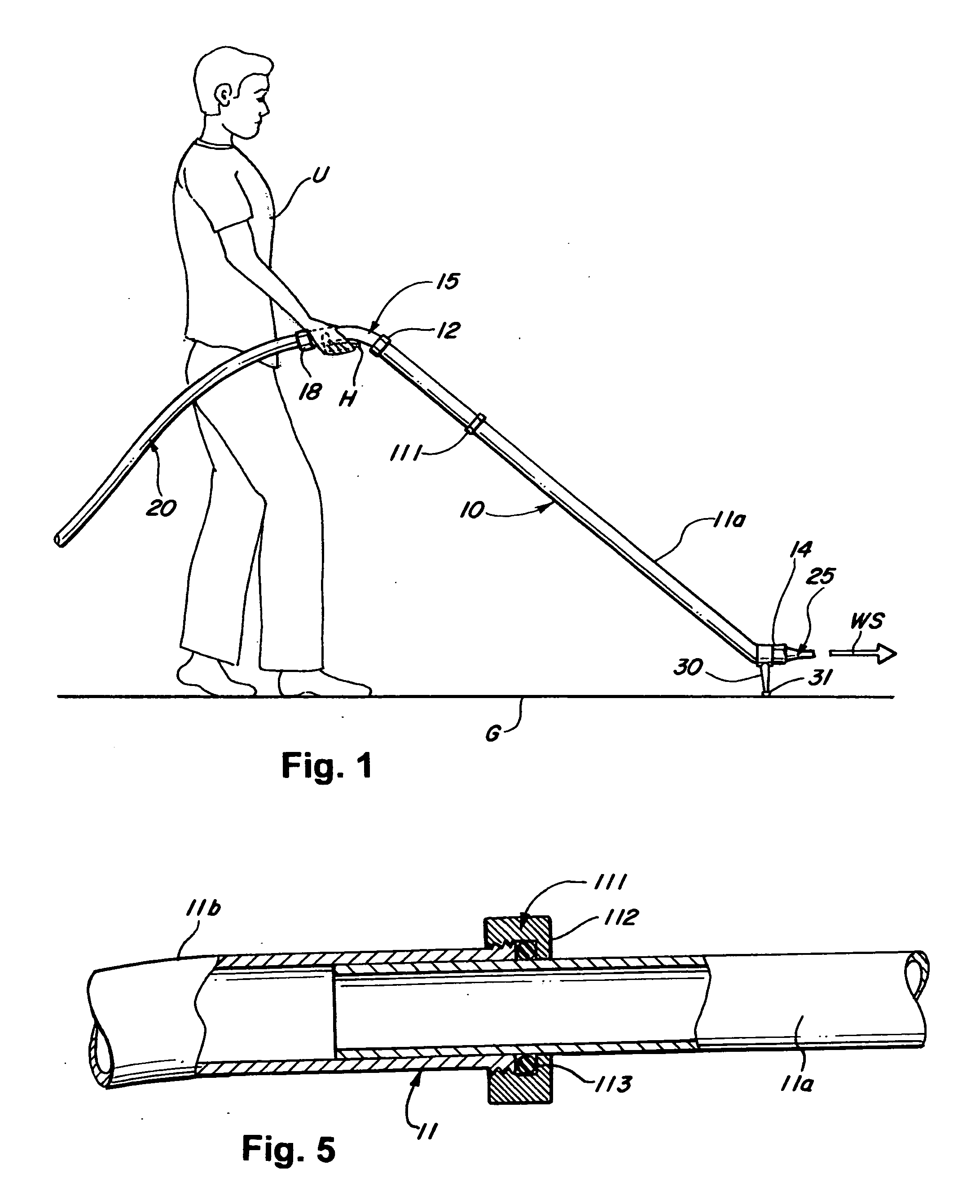
[0014]Preferably the wand length, the arcuate dimension of the handle, the relative nozzle inclination and the pivot post are all selected to comfortably deploy the nozzle adjacent the ground easily turned along various azimuths and elevations with the forces transferred through the pivot post contact against the ground surface that is to be swept by the stream emitted from the nozzle then opposing all the reactive forces. Thus the selection of angles and dimensions is such that with the handle comfortably grasped by the user and the lever manually articulated to initiate the flow the resulting increased wand weight and the nozzle reaction forces are all opposed by the pivot post contact against the ground. By selecting a wand length of about 3 feet, with the handle then held by a person of an average height, all these geometric advantages are conveniently obtained, easing the tiring task of protracted water stream sweeping of large areas.
[0015]Those skilled in the art will appreciate that the task of sweeping a large surface area is a formidable, time consuming task that is best achieved with the aid of fairly robust water jets. These, however, invariably generate a substantial opposing reaction forces that need to be closely controlled as the efficacy of the cleaning depends greatly on the accuracy with which this highly focused and highly erosive water stream is aimed. The user engaged in such an endeavor will be quickly exhausted unless the stream forces are conveniently opposed by the geometry of the nozzle supporting post that also provides the desired weight offsets that reduce the moment resisted at the user's arm.
[0016]In particular, the selection of a generally S-shaped wand of a length that is somewhat greater than the typical distance between the hand of the user and the surface that is to be cleaned a wand inclination is effected where the wand weight, including that of the water volume contained, adds to the contact force at the supporting post end while also countering the stream force moment. Thus the nozzle is conveniently aligned adjacent the ground surface that is being cleaned in a manner where only small arm or hand manipulations are needed to control the stream direction.
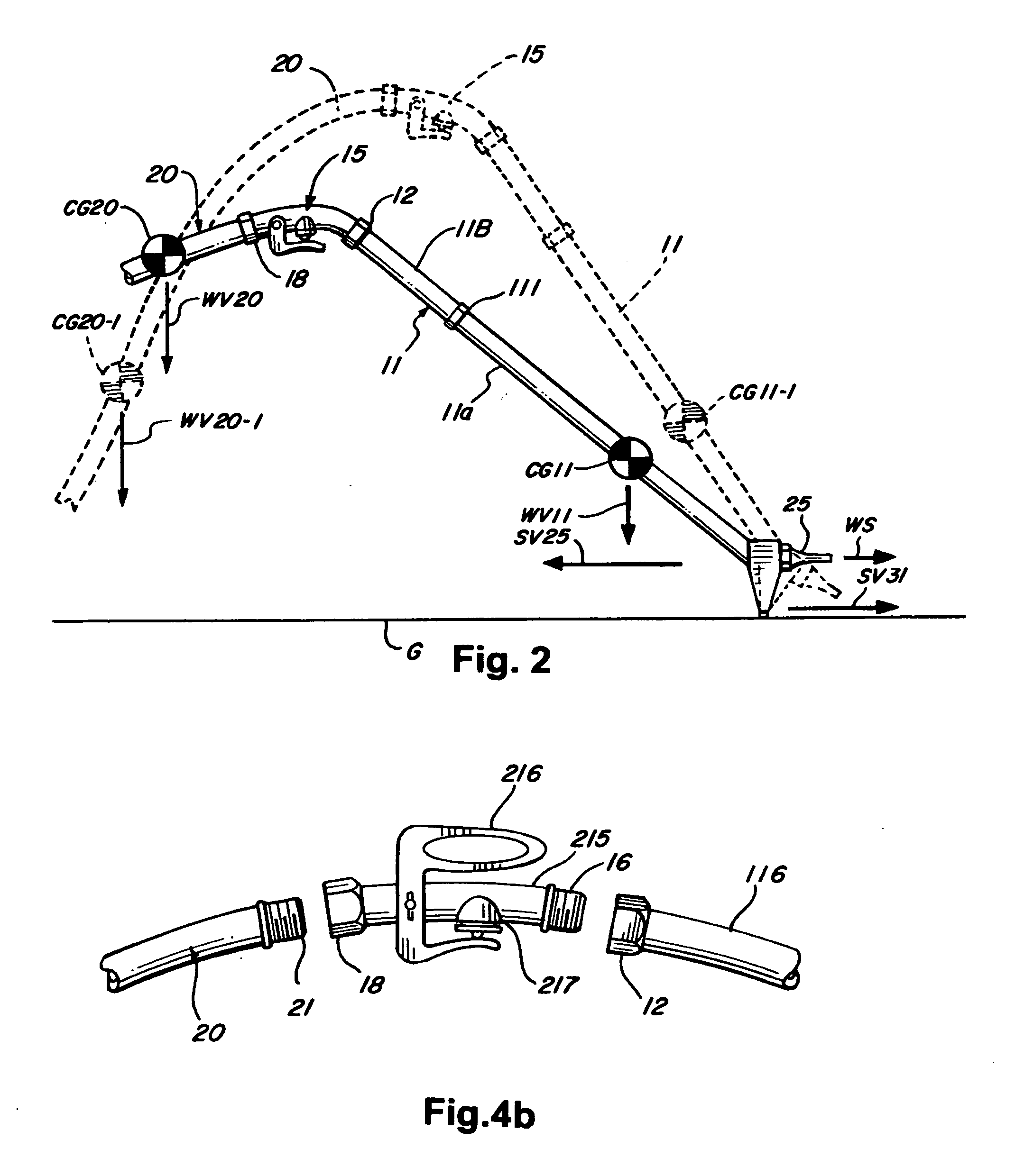
[0017]In this manner an inexpensively produced and convolved tubular segment provided with conventionally available hose fittings at both ends can be conveniently inserted between the end of a garden hose and a commercially obtainable nozzle assembly to form a self supported sweeper structure that opposes the nozzle stream. A similarly conventionally available valve at the hose end can be also included in the assembly, modified to include an extended control lever to resolve all the burdens of protracted handling of a sweeper that entails the use of a focused, high volume and therefore vigorous water stream.

Problems solved by technology

A well focused, high pressure stream, however, is always associated with a reactive force and the task of controlling this force is both difficult and tiring, particularly when the slope angles of the cleaned surface, the amount of debris accumulated and the distances that it needs to be moved all demand long intervals of crouched or leaning body postures.
Of course, persistent retention of these geometric alignments of a high flow rate nozzle is extremely tiring and various support structures have been devised in the past which in one way or another assist in the task.
Moreover, while suitable for the purposes intended, each of the foregoing teachings is clearly directed to a very specific spray pattern and are therefore functionally limited to very small directional changes in the course of their use.
Those prior art devices that deploy the spray head directly on the ground surface, as exemplified in the teachings of US patents 5,477,583 to Deloe; 4,982,896 to Crow; and 2,289,889 to Stick et al., while also suitable for the purposes intended, lack the structural configuration and geometric range to allow for protracted directional alignments of the stream within the confines of human anatomy.
In consequence, little attention has been devoted to the manipulative task of debris sweeping of large surfaces by a high pressure stream and few devices are available that fully simplify this task.

Method used


Image

  • Water jet sweeper
  • Water jet sweeper
  • Water jet sweeper

Examples


Embodiment Construction

[0023]As shown in FIGS. 1-3 the inventive water stream sweeping assembly generally designated by the numeral 10 includes an elongate tubular element or wand 11 in the form of a hollow tube generally convolved longitudinally into an S-shaped form and provided with a female threaded fitting 12 at one end and a male threaded fitting 14 at the other end. Preferably, the female fitting 12 is conformed to receive a threaded male outlet end 16 of a valve assembly 15 which at the other end 18 connects to the end 21 of a garden hose 20 while a conventional focused stream nozzle 25 is mounted on the male threaded fitting 14 at the other end of the wand.

[0024]A short, generally tapered, support post 30 is fixed to the wand 11 adjacent the end fitting 14, extending generally orthogonally to the exterior of the local wand convolving curvature to form a supporting contact at its small free end 31 with the ground surface G. Preferably, the wand length, the post height, its relative inclination, th...


PUM


Abstract

A water stream ground sweeping assembly includes a generally S-shaped tubular wand provided with an outlet nozzle at one end and connected at the other en across a control valve to a flexible water conveying hose with the length and the convolutions of the wand being selected to align the control valve with the suspended palm of an erect person. The arcs of the S-convolutions are further selected so that the nozzle raised above ground by a proximately located support post is pointing generally horizontally when the valve is grasped by the suspended palm. When, however, the palm of the person is raised the resulting increased weight of the unsupported hose increment unloads the post contact to create the perception of an impending loss of control in the palm, thus limiting the incidents of ground eroding nozzle alignments.

Description

REFERENCE TO RELATED APPLICATIONS[0001]This application obtains the benefit of the earlier filing date of Provisional Patent Application No. 61 / 399,114 filed on Jul. 7, 2010.BACKGROUND OF THE INVENTION[0002]1. Field of the Invention[0003]The present invention relates to water stream directing mechanisms and more particularly to manually directed structures for deploying the jet of a debris sweeping water stream adjacent the surface that is being swept while also retaining full manipulative convenience over the selection of its angle of incidence and also its horizontal direction.[0004]2. Description of the Prior Art[0005]High pressure, narrowly focused and precisely directed water streams have been widely used to wash various surfaces and also as sweeping mechanisms to remove the loosened debris and dirt therefrom, with the usefulness of this cleaning process now even further enhanced by various augmentation mechanisms that increase its pressure. Simply, a garden hose with a well sh...

Claims


Application Information

Patent Timeline
Patent Type & Authority Applications(United States)
IPC IPC(8): B05B1/14
CPCB05B15/066B05B15/063B05B15/625B05B15/652
Inventor CARR, DOUGLAS
Owner CARR DOUGLAS
Learn More