Magnetically Actuated Reciprocating Motor and Process Using Reverse Magnetic Switching

Inactive Publication Date: 2012-01-12
GOSVENER KENDALL C
View PDF8 Cites 12 Cited by
  • Summary
  • Abstract
  • Description
  • Claims
  • Application Information

AI Technical Summary

Benefits of technology

[0023]It is also an object of the present invention to provide a magnetically actuated reciprocating motor that does not require utilization of

Problems solved by technology

The present magnetically actuated reciprocating motor does not utilize an electromagnet and, as a result, eliminates the problems associated with the per

Method used


Image

  • Magnetically Actuated Reciprocating Motor and Process Using Reverse Magnetic Switching
  • Magnetically Actuated Reciprocating Motor and Process Using Reverse Magnetic Switching
  • Magnetically Actuated Reciprocating Motor and Process Using Reverse Magnetic Switching

Examples


Example

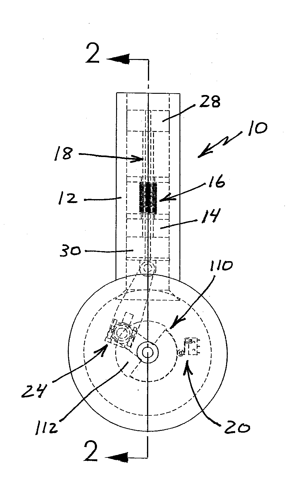
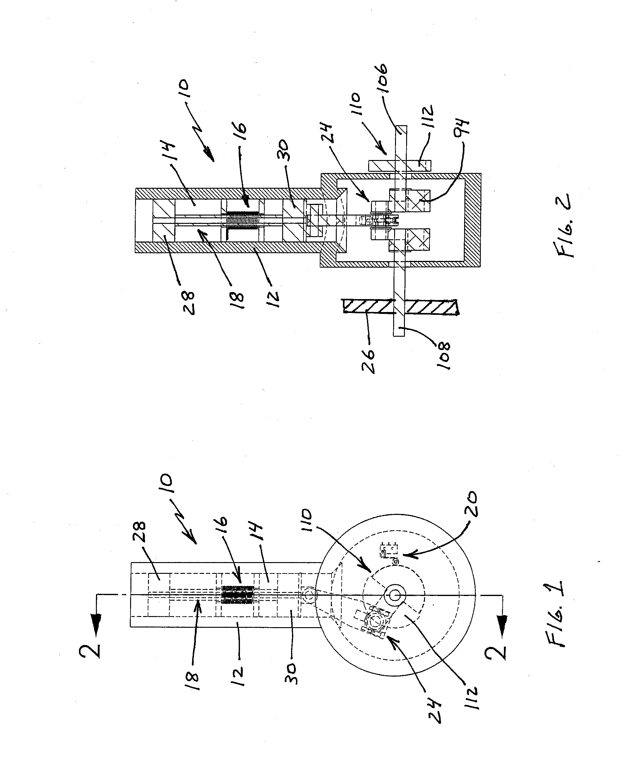
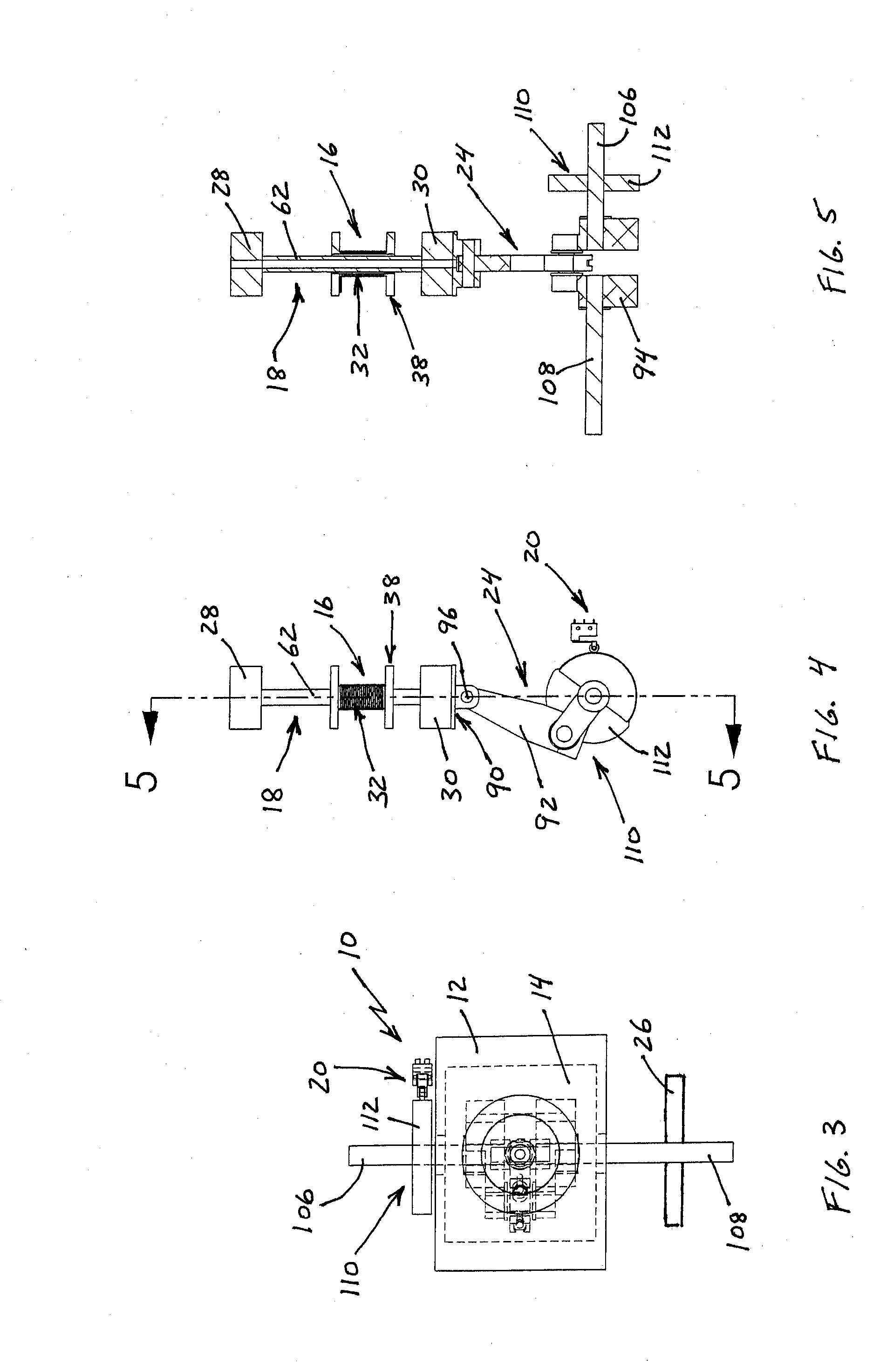
[0050]With reference to the figures where like elements have been given like numerical designations to facilitate the reader's understanding of the present invention, the preferred embodiments of the present invention are set forth below. The enclosed text and drawings are merely illustrative of preferred embodiments and only represent several possible ways of configuring the present invention. Although specific components, materials, configurations and uses are illustrated, it should be understood that a number of variations to the components and to the configuration of those components described herein and in the accompanying figures can be made without changing the scope and function of the invention set forth herein. For instance, the figures and description provided herein are primarily directed to a single motor, however, those skilled in the art will readily understand that this is merely for purposes of simplifying the present disclosure and that the present invention is not...


PUM


Abstract

A magnetically actuated reciprocating motor utilizes the stored energy of permanent magnets and an electromagnetic field to reciprocally drive a magnetic actuator. A converting mechanism converts the reciprocating motion of the magnetic actuator to rotary motion for powering a work object. A solenoid, comprising a nonferromagnetic spool having a tubular center section with a coil of wire wrapped around the center section, is connected to a source of power and a switching mechanism. The magnetic actuator has permanent magnets disposed inside a tubular shaft at each end thereof. The switching mechanism switches the magnetic polarity at the ends of the solenoid to alternatively repel and attract the permanent magnets. The shaft is reciprocatively received through the center section of the solenoid. A controlling mechanism interconnects an output shaft, rotatably powered by the magnetic actuator, and the switching mechanism to switch the polarity of the solenoid to drive the magnetic actuator.

Description

CROSS-REFERENCE TO RELATED APPLICATIONS[0001]This patent application is a continuation-in-part of U.S. patent application Ser. No. 12 / 832,928 filed Jul. 8, 2010.STATEMENT REGARDING FEDERALLY SPONSORED RESEARCH[0002]Not Applicable.REFERENCE TO A SEQUENCE LISTING, A TABLE OR A COMPUTER PROGRAM LISTING APPENDIX SUBMITTED ON A COMPACT DISC[0003]Not Applicable.BACKGROUND OF THE INVENTION[0004]A. Field of the Invention[0005]The field of the present invention relates generally to reciprocating motors which utilize a drive mechanism to provide power to an output shaft or crankshaft. More particularly, the present invention relates to such motors in which the magnetic repelling and attracting forces of permanent magnets are utilized to reciprocate a magnetic actuator. Even more particularly, the present invention relates to such motors in which the change in direction of the actuator is obtained by utilizing an axially charged solenoid to alternatively repel or attract the actuator.[0006]B. ...

Claims


Application Information

Patent Timeline
IPC IPC(8): H02K7/075
CPCH02K33/16H02K7/075H02K7/06
Inventor GOSVENER, KENDALL C.
Owner GOSVENER KENDALL C
Why Eureka
Try Eureka