Apparatus for automatically separating and detecting noise radio waves

Active Publication Date: 2012-01-12
KUMAGAI HIDEKI
View PDF13 Cites 3 Cited by
  • Summary
  • Abstract
  • Description
  • Claims
  • Application Information

AI Technical Summary

Benefits of technology

[0024]The present invention has been made to solve the problems in the old invention, and it is an object of the present invention to provide an apparatus that effectively extracts noises generated from the natural world.
[0025]That is, in order to easily and automatically separate and detect the noises generated from the natural world, a received high-frequency waveform of AM modulation is separated into two systems, independent processing is performed on the waveform of each system, and the waveforms of the two systems are subtracted, thereby making the high-frequency noise portions other than the signal waveforms distinctive to detect the noises. When the noises are detected, the low-frequency envelope is not used and only the high frequency processing is executed, and the portion corresponding to the “dead zone” is not generated. The noises can be automatically separated and detected, regardless of the generation time of the high-frequency noises, an

Problems solved by technology

However, in this system, the electromagnetic wave noises that functions as a predictor of the earthquake may not be sufficiently detected.
In the electromagnetic waves of broadcasting and communication frequency bands subjected to AM modulation, in the case where the configuration where the noises are detected by a

Method used


Image

  • Apparatus for automatically separating and detecting noise radio waves
  • Apparatus for automatically separating and detecting noise radio waves
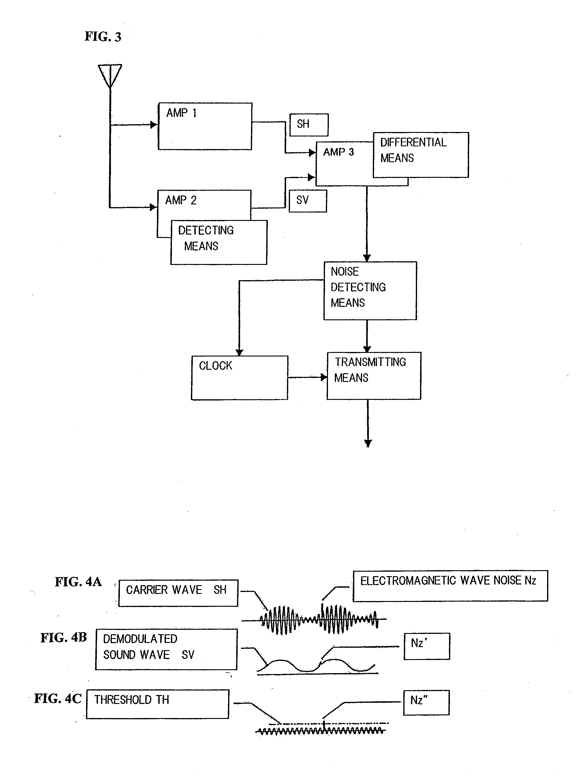
  • Apparatus for automatically separating and detecting noise radio waves

Examples


first embodiment

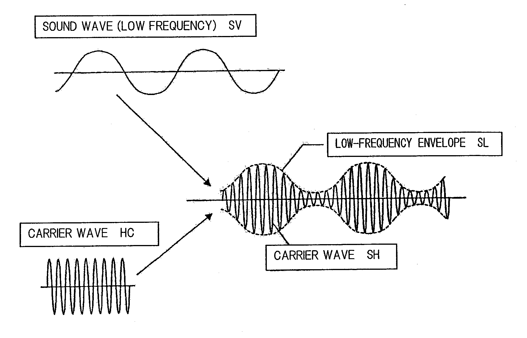
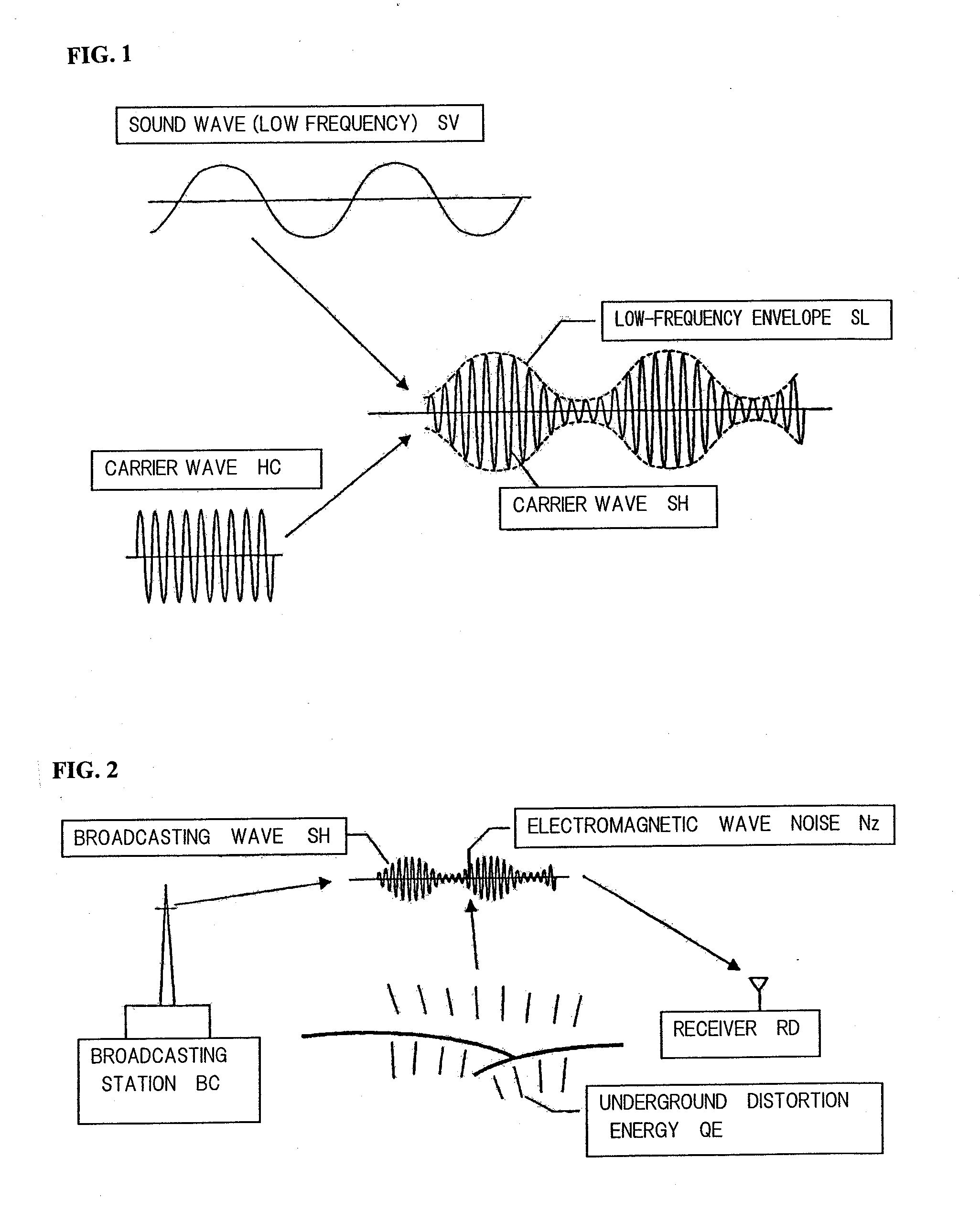
[0048]The case where a high-frequency noise NzB illustrated in FIG. 5 or 6 is mixed with a high frequency carrier wave SH (broadcasting wave) subjected to low frequency modulation, such as a sound wave, SV as illustrated in FIG. 1 is considered.

[0049]In FIG. 7, the high frequency carrier waves SH are received by a tuning circuit TUNE to the frequency SH, a radio wave signal that is output by an initial stage amplifying circuit AMP1 is amplified by a high-frequency amplifying circuit having an inversion output, such as AMP2, and an output signal SHS of a regular output side and an output signal SHR of an inversion output side are obtained. If a balance of the output signals SHS and SHR is adjusted, the output signals SHS and SHR where the waveforms are inverted with the same waveforms can be obtained as illustrated in the waveforms of FIGS. 8 and 9.

[0050]In this stage, the waveforms of the high-frequency noises that are mixed as illustrated in FIGS. 8 and 9 are inverted with the same...

second embodiment

[0060]The above-described first embodiment is realized by using the method that uses the signal subtraction, specifically, generates inverted inverse phase signals and adds the signals by (1) amplifying the tuning frequency with the high frequency and separating the frequency into two systems, (2) independently amplifying the separated output waveforms of the two systems by the amplifiers having the different frequency characteristics, (3) adjusting the amplitudes and the phases of the tuning frequencies of the independently amplified outputs of the two systems, and (4) subtracting both of the signals and making the output of the tuning frequency portion become approximately zero.

[0061]Meanwhile, the second embodiment is realized by using a method that subtracts the signals having the same phase with the differential amplification.

[0062]That is, in the second embodiment, a tuning amplification mechanism configuration of the initial stage is the same as that of the first embodiment, ...

third embodiment

[0072]The above-described embodiments are related to the method for automatically separating and detecting the high-frequency noises by the cancellation of the regular signal and the inversion signal. However, in this embodiment, the noises are detected by the tuning frequency cancellation by the signals having the phase shift of 180°, instead of the inversion signal.

[0073]In FIG. 18, if the phase of the SHS-A where the noise NzBs-A exists on the original regular signal waveform is delayed by 180°, the SHS-B is obtained.

[0074]If this is applied to the frequency band having the high phase shift, the high-frequency noise NIBS is also delayed by 180°. Therefore, 180° delay is generated in the waveform of the high-frequency noise like the NzBS-C. If it is assumed that the phase shift is not generated in the high frequency component, the signal remains with the same phase as the NzBS-A like NzBS-D.

[0075]In this case, if the SHS-A and the SHS-B having the 180° phase shift from the SHS-A a...


PUM


Abstract

An output signal SHS is secondarily amplified by a high-frequency amplifier AMP3 and an output signal SHR is secondarily amplified by an AMP4 for which high-frequency side amplitude reducing means is taken. In this case, the AMP4 has small gain of a high-frequency region and its output SHR-2 is reduced in amplitude. However, a high-frequency noise has a frequency higher than that of a carrier wave SH and the amplitude of a noise NzB becomes smaller. The other output signal SHS is directly amplified by the wideband amplifier AMP3. The width of an SHS-2 and the width of the SHR-2 are adjusted by amplitude adjusting means throughout the whole region and then mutually added by both signals addition amplifying means again so that the amplitude of the output signal SHS is adjusted to the SHR-2, and a predetermined threshold value is set to extract the noises.

Description

BACKGROUND OF THE INVENTION[0001]The present invention relates to an apparatus for detecting electromagnetic waves that are generated due to activity in the natural world. More particularly, the present invention relates to an apparatus for detecting a change of electromagnetic waves generated as a premonitory symptom of earthquakes.[0002]By the movement of various plates constituting the earth crust of the earth, complicated stress occurs between the plates. In particular, Japan undergoes a large-scale earthquake regularly because of being located in the place where the plural plates interfere with each other, and gets into danger. From such a point of view, the prediction of the earthquake is extremely important and urgent. However, unfortunately, the earthquake prediction to specify the time and the place of the earthquake generation is not yet possible at the current science standard.[0003]In regards to an earthquake prediction method based on the earthquake prediction or the ob...

Claims


Application Information

Patent Timeline
IPC IPC(8): H03F3/68
CPCH04B1/12G01V3/12
Inventor KUMAGAI, HIDEKIKUMAGAI, TAKASHI
Owner KUMAGAI HIDEKI
Why Eureka
Try Eureka